8.8“ Touchscreen Colour Display AHD 880 TC
Technical Information
24
V5
4.5
Connections
4.5.1 Device Connections
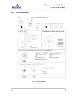
A 2 m long cable (LiYY 9 x 0.75 mm²) is led out through a cable
bushing (M16). It is responsible for the 24 V DC power supply, the
connection of the control outputs “horn” and “group alarm,” and the
contact input for alarm acknowledgement.
Two supply inputs of equal priority (supply 1, supply 2) are avail-
able. They are galvanically uncoupled from one another through in-
ternal switching logics. Therefore, in case of dual engine propul-
sion systems, the corresponding engine battery can be directly ac-
cessed as a power source. The system is automatically fed by one
of these sources, independently of which engine is currently active
– or whether both engines are active.
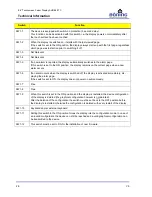
The independent CAN-bus systems (CAN 1, CAN 2 and CAN 3)
can be connected with a corresponding 5-pin plug connector
(
plug), according to “DeviceNet Standard.” The CAN-bus handles
the data transfer and communication with all other devices con-
nected to the system. The system configuration is also uploaded
via the CAN-bus. Prior to upload, it is created with a separate con-
figuration software.
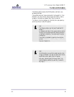
If present, Remote Control AHD 650R is connected to the device
with the 8-pin plug.
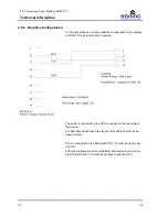
The integrated RS232 interface is primarily used for connecting an
external GPS receiver. The data transmitted by the GPS receiver
can be used to calculate and display e.g. cruising speed and dis-
tance related fuel consumption.
The Color Display AHD 880 TC’s firmware is uploaded via an
RS232 interface located behind a plastic covering on the device
rear.
As far as the color display’s serial interfaces are concerned: the
Color Display AHD 880 TC is a terminal device. This means that a
1:1 cable must be used (not a twisted wire, null modem cable or
lap link).

