IP50HD
USER MANUAL
Contact:
|
|
05
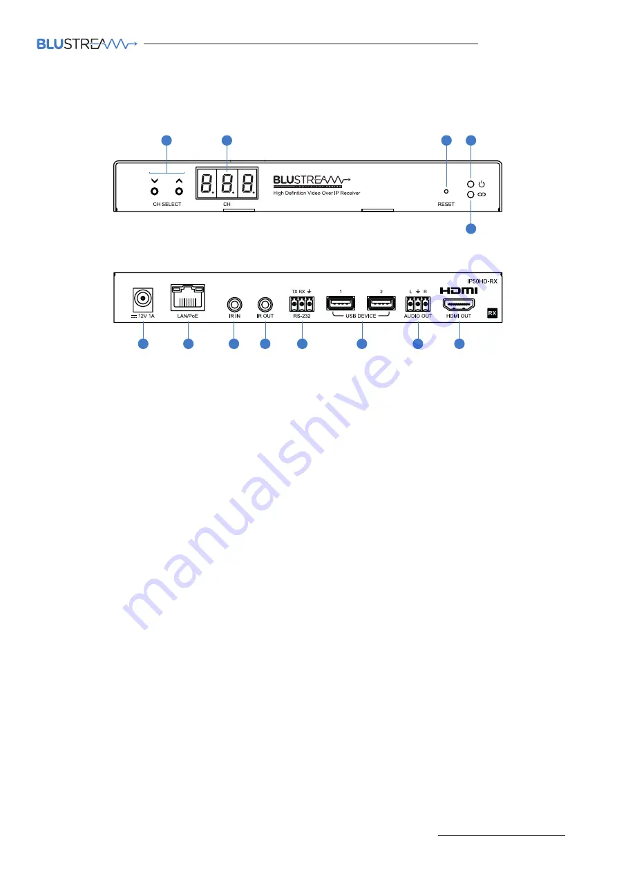
IP50HD-RX Front Panel
1
Channel Select Up/Down - configure IP50HD-RX manually and select channel of TX to view
2
Channel status window - displays product information
3
Reset button - short press to restart / reboot device, press and hold for 10 seconds to factory reset device
4
Power LED indicator
5
Link LED indicator - solid status light indicates a stable connection to the network switch
6
Power port – use 12V 1A DC adaptor (sold separately) if not using a PoE network switch
7
LAN Connection (PoE) - connect to network switch for HDMI video distribution
8
IR IN (IR input) – 3.5mm stereo jack. Transmits IR to the IP50HD-TX transmitter currently selected. Supports 5V or
12V IR selectable in product web-GUI or ACM200 web-GUI
9
IR OUT - (IR output) - 3.5mm mono jack – routed IR from any IP50HD-TX (source) allowing display control. Supports
5V or 12V IR selectable in product web-GUI or ACM200 web-GUI
q
Assignable bi-directional RS-232 port – connect to third party control device to extend RS-232 commands to any/
multiple IP50HD Multicast products RS-232 port
w
USB device connection for USB/KVM routing within Multicast system
e
L/R Analogue audio line output - 2ch audio that supports 2ch PCM source inputs
t
HDMI output - connect to display device
IP50HD-RX Rear Panel
Panel Description - IP50HD-RX Receiver
11
10
9
8
6
2
1
3
4
5
87
13
12


