background image

65

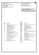
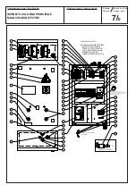
TAVOLE PEZZI DI RICAMBIO

SPARE  PARTS  TABLES

ERSATZTEILELISTEN

PLANCHES DES PIECES DE RECHANGE

TABLAS DE LAS PIEZAS DE REPUESTO

COME ORDINARE UN PEZZO DI RICAMBIO

Per


ordinare


un


pezzo


di


ricambio


occorre


fornire


al


rivenditore

autorizzato


il


n° di codice 

corrispondente,


che


deve


essere


rica-

vato


consultando


la


tavola


relativa


posta


all

’

interno


del


manuale

ricambi.

La


tavola 

(

identifi


cata


da


n

° 

e


indice


di


revisione

)


deve


essere

selezionata


consultando


l

’

Indice delle tavole 

posto


all

’

inizio


del

manuale


ricambi.

A


tale


scopo


occorre


conoscere:

il


modello 

ed


il


n° di matricola 

della


macchina


cui


il


ricambio

è


destinato


(

riportati


negli


appositi


campi


sulla


targhetta matri-

cola

)

-


il


gruppo


funzionale


di


cui


fa


parte


il


pezzo


(

facendo


riferimento

all

’

Indice figurato 

posto


all

’

interno


del


manuale


ricambi

)

.

HOW TO ORDER SPARE PARTS

W

hen


ordering


spare


parts,


please


always


indicate


the

relevant


part  number 

to


the


authorised


dealer.


The

number


is


to


be


found


in


the


relevant


table


in


the


Spare

Parts


manual.

The


table 

(

identifi


ed


by


a


number


and


a


revision


index

)

must


be


selected


among


the


ones


in


the


tables

summary 

at


the


beginning


of


the


spare


parts


manual.

In


order


to


choose


the


appropriate


table,


you


must


know

the


following:

- Machine 

model


and 

serial


number


(indicated on the

serial


number


plate

).

-


F

unctional


unit


to


which


the


part


belongs


(

please


refer

to the 

detailed


view


in the spare parts manual).

Ai


fini


di


una


corretta


gestione


dei


rischi


residui


sono


ricollocati


sulla


macchina


pittogrammi


per


il


rilievo


di


quelle

zone


suscettibili


di


rischio


in


fase


operativa.

Q

ueste


indicazioni


sono


fornite


su


etichette


autoadesive


che


recano


un


proprio


codice


di


identificazione.

Importante: 

nel


caso


in


cui


le


etichette


venissero


smarrite


o


diventassero


illeggibili


si


prega


di


ordinarle


alla


casa

costruttrice


e


ricollocarle


secondo


lo


schema


riportato


nelle


pagine


seguenti.

ATTENZIONE!

F

or


a


correct


handling


of


residual


risks,


pictograms


are


located


on


the


machine


to


show


the


areas


subject


to


risk

during


operation.

These


indications


are


supplied


on


self-sticking


labels


bearing


an


identifi


cation


code.

Important: 

should


the


labels


be


lost


or


become


illegible,


please


order


replacements


from


the


manufacturer


and

attach


them


as


shown


in


the


diagram


in


the


following


page


(

Tab.


10

)

.

WARNING!

F

ür


eine


korrekte


Verhaltensweise


bei


den


noch


bestehenden


Risiken


zeigen


Bilderschriftzeichen


auf


der


Ausrüstung

an,


welche


Zonen


während


des


Betriebs


Gefahrenquellen


darstellen


k

ö

nnten.

Diese


Hinweise


fi


nden


Sie


auf


Selbstkiebeetiketten,


die


über


eine


eigene


Identifi


kationscode


verfügen.

Wichtig: 

Bei


Verlust


oder


Unleserlichkeit


der


Etiketten


bestellen


Sie


diese


bitte


bei


der


Herstellerfi


rma


und


brigen


sie

gemäss


dem


oben


aufgeführten


Schema


auf


den


folgenden


Seiten


an


(

Tab.


10

)

.

ACTUNG!

Pour


assurer


une


gestion


correcte


des


risques


résiduels,


des


pictogrammes


sont


appliqués


sur


la


machine


pour

signaler


les


zones


susceptibles


de


risque


en


phase


de


fonctionnement.

Ces


informations


sont


fournies


sur


des


étiquettes


autocollantes


qui


portent


chacune


un


code


d

’

identifi


cation.

Important: 

en


cas


de


perte


des


étiquettes


ou


si


elles


deviennent


illisibles,


les


commander


chez


le


fabricant


directement

et


les


appliquer


sur


la


machine


en


suivant


le


schéma


dans


les


pages


suivantes


(

Tab.


10

)

.

ATTENTION!

Con


el


fi


n


de


una


correcta


gesti

ó

n


de


los


riesgos


residuos,


est

á

n


colocados


en


la


m

á

quina


pitogramas


para


el

relievo


de


las


zonas


suceptibles


de


riesgo


en


fase


operativa.

Estas


indicaciones


se


abastecen


en


etiquetas


autoadhesivas


que


tienen


un


propio


c

ó

digo


de


identifi


caci

ó

n.

Importante: 

en


el


caso


que


las


etiquetas


se


perdieran


o


se


volvieran


invisibles


se


ruega


pedirlas


a


la


casa


constructora

y


volverlas


a


colocar


seg

ú

n


el


esquema


indicado


en


las


p

á

ginas


siguientes

(

Tab.


10

)

.

ATENCIÓN!

Summary of Contents for MRG25-4

Page 1: ...ENTES ITALIANO ISTRUZIONIORIGINALI ENGLISH TRANSLATION OF THE ORIGINAL INSTRUCTIONS DEUTSCH BERSETZUNG DER ORIGINALANLEITUNG FRAN AIS TRADUCTION DES INSTRUCTIONS ORIGINALES ESPA OL TRADUCCI N DE LAS I...

Page 2: ...aufbewahrt werden DieAnleitung an einem bekannten und leicht zug nglichen Ort aufbewahren und bei Bedarf zu Rate ziehen Alle Bediener des Ger ts m ssen zwecks Einsichtnahme Zugang zur Anleitung haben...

Page 3: ...t angemessene Handschuhe tragen Der Arbeit a n g e m e s s e n e Schuhe tragen Sich nicht unter gehobener Last aufhalten oder durchgehen Q u a l i f i z i e r t e s Fachpersonal Achtung Mechanische Or...

Page 4: ...to use 5 CHECKINGTHEMINIMUM REQUIREMENTS FOR THE PLACE OF INSTALLATION 6 INSTRUCTIONSFORUSE 6 1 Installation requirements 6 2 Voltage check 6 3 Connecting up to the mains 7 INSTRUCTIONSFORUSINGTHELIFT...

Page 5: ...56789012123456 1234567890123456789012345678901212345678901234567890123456789012123456 1234567890123456789012345678901212345678901234567890123456789012123456 1234567890123456789012345678901212345678901...

Page 6: ...eitseinrichtungen sind verboten Bei Verstoss gegen diese Vorschriften lehnt der Hersteller jede Verantwortung f r die daraus entstehenden Sch den ab Dar ber hinaus sind folgende Verhaltensmassregeln e...

Page 7: ...der S ule Dieses Schutzgeh use vermeidet dass der Bediener w hrend des Betriebs der Hebeb hne mit den H nden an die Spindel gelangt die Spindel dreht sich mit sehr niederer und daher nicht besonders g...

Page 8: ...ndschalter nicht funktionieren wird die Hebeb hne ber ein mechanisches Sperrsystem abgestoppt Unter diesen Umst nden die Hebeb hne in umgekehrter Richtung ugf 5 10 cm sto weise zur ckfahren Den Endsch...

Page 9: ...f r die Tragmutterabnutzung ein Der Eingriff der Vorrichtung f hrt zu einer Notfall Blockierung 1 8 Abschaltung bei Hindernis St t der Hubwagen auf ein Hindernis welches dessen Herunterfahren verhind...

Page 10: ...nts recommended by the vehicle manufacturer use optional adapters There must be No one on the lift or in the vehicle when lifting Press the UP button Before the adapters make contact with the vehicle...

Page 11: ...NESAVAILABLE FROM THE MANUFACTURER 1 9 Auf der Hebeb hne vorhandene Gefahrenzeichen SIEHE ABB EVTL BESCH DIGTE GEFAHRENZEICHEN SIND BEI DER FIRMA ANZUFORDERN UND ZU ERSETZEN 1 9 Pictogramas presentes...

Page 12: ...12 2 Kg 2500 1 1...

Page 13: ...Hersteller angegebenen Bestimmungen entsprechen Die Verwendung abweichender Ausma e muss mit dem Hersteller abgestimmt werden oder es m ssen optionale Anpassvorrichtungen angebracht werden Im Fall vo...

Page 14: ...14 3 Pagina bianca per esigenze di impaginazione This page intentionally blank Freie Seite f r Layout Page blanche pour exigences de mise en page P gina en blanco por exigencias de compaginaci n...

Page 15: ...Tragkraft 2500 kg Drehstrommotor 230 400 V 50 Hz 3 5 kW Gewicht max S ulen 410 kg Ger uschpegel 70 dB A 3 DATOS T CNICOS MRG25 4 Capacidad 2500 kg Motor Trif sico 230 400 V 50 Hz 3 5 kW Peso m x Colu...

Page 16: ...nels 3 1 Transport und Installationsvorbereitung Angemessene Kleidung anlegen und pers nliche Schutzma nahmen treffen Die Hebeb hne wird in waagrechter oder senkrechter Lage in einer Kiste verpackt an...

Page 17: ...gure fino a portare il sollevatore in posizione verticale Eseguire le operazioni con molta attenzione e lentamente After unpacking check the lift for possible damages and make sure that all accessorie...

Page 18: ...ificando la posizione della vite T Togliere il golfare di sollevamento e montare il carter motore Montare i salvapiedi e il supporto cavo elettrico Secure the control panel Assemble and secure the bas...

Page 19: ...vo sulle forche e sollevare la colonna N B Il mezzo di sollevamento deve poter raggiungere un altez za minima di 3000 mm Screw the lifting eyebolt position the cable on the forks and lift the post Not...

Page 20: ...ue la position est correcte Desenroscar todos los pernos presentes en la base prestando atenci n a su posici n para volverlos a colocar correctamente Atornillar y apretar todos los pernos que fijan la...

Page 21: ...re Montare i salvapiedi Montare il carter e fissarlo mediante le apposite viti avendo cura di montare nella parte bassa il supporto transpallet Remove the lifting eyebolt and fit the motor guard Fit f...

Page 22: ...22 1 2 3 1...

Page 23: ...und einer auf dem Stab gegen ber ausgerichtet sind siehe Abschnitt 9 Das Schutzgeh use 2 schlie en den Palettenhubwagenhalter 1 montieren und falls noch nicht vorhanden die Fu abweiser anbringen Den...

Page 24: ...24 1 2 3 9 4 5 6 8 4 6...

Page 25: ...tellen Hebe und Senkbewegungen ber Bronzetragmuttern 5 die an Spindeln mit feiner Gewindesteigung gekoppelt sind um die Unumkehrbarkeit der Bewegungen sicherzustellen Elektrischer Endschalter 6 zur un...

Page 26: ...fungen auf jeden Fall ausgef hrt werden ist dieses Produkt gem der Europ ischen Richtlinie 2006 42 CE gebaut worden Gem dem Artikel 4 1 2 3 der o g Richtlinie sind folgende Koeffizienten f r die Pr f...

Page 27: ...dort die gesamte Einrichtung und das Arbeitsfeld berblicken k nnen muss Er muss daf r sorgen dass sich in diesem BereichkeineunbefugtenPersonenaufhaltenoderGegenst ndebefinden dieGef hrdungenhervorruf...

Page 28: ...28 6 Q R1 R1 Q 3000 kg R1 1400 kg S2 S3 S4 P1...

Page 29: ...riore a 25 mm d Portanza del terreno non inferiore a 1 3 kg cm2 Le caratteristiche esposte debbono essere garantite su di una area minima di di m 4 00x1 50 nella quale non debbono essere presenti giun...

Page 30: ...0 230 0 2 1 15 9 R T AZZURRO TENSIONE MAGGIORE HIGHER VOLTAGE TENSIONE MINORE LOWER VOLTAGE BIANCO ROSSO AZZURRO BIANCO ROSSO AZZURRO BIANCO ROSSO AZZURRO BIANCO ROSSO 230V 50 HZ 220V 60 HZ 400V 50 HZ...

Page 31: ...ank anschlie en Den Hauptschalter auf ON schalten falls auf der Schalttafel die wei e Kontrolllampe nicht aufleuchtet die zwei Leiter auf dem Klemmenbrett umtauschen 6 3 1 Speisungskabel Siehe Tabelle...

Page 32: ...32 6 led7 led6 led5 led4 led3 led2 led1 MANUALE MANUAL AUTOMATICO AUTOMATIC S 2 P 1 SCA1 MASTER JP700 1 6 ON OFF S 3 S 4 M E B D C A...

Page 33: ...tore si trova in condizione di blocco possibile far scendere singolarmente i carrelli di ciascun sollevatore Ruotare su 0 l interruttore generale Aprire la porta del quadro di comando Sulla scheda spo...

Page 34: ...34 6 led7 led6 led5 led4 led3 led2 led1 MANUALE MANUAL AUTOMATICO AUTOMATIC S 2 P 1 SCA1 MASTER JP700 1 6 ON OFF S 3 S 4 M E B D C A...

Page 35: ...t vermieden werden k nnen Vorsicht w hrend des einzelnen Abstiegs darf die schlechte Ausrichtung der Wagen nie 50 mm berschreiten Der letzte Wagen der am Boden ankommt am Endanschlag des Abstiegs setz...

Page 36: ...36 6 E B D C A led7 led6 led5 led4 led3 led2 led1 S 2 P 1 SCA1 MASTER JP700 1 6 ON OFF S 3 S 4 1 ON 6 OFF S 2 P 1 S 3 S 4...

Page 37: ...ica abrir la puerta del cuadro de mando en la ficha colocar los switch como se indica en la figura switch 1 en ON switch 2 3 4 5 6 en OFF Presionar simult neamente los pulsadores P1 S2 S3 S4 y suminis...

Page 38: ...ONTELEVATEUR 7 1 Utilisation incorrecte de l l vateur L l vateur est destin au levage de v hicules dont les caract ristiques correspondent aux Caract ristiques techniques et au paragraphe Destination...

Page 39: ...litate the work of the operator Only original accessories can be used made by the manufacturer When ordering the machine you should know whether vehicle lift crosspieces are to be used since this is o...

Page 40: ...rrectement et en toute s curit il est indispensable que le personnel pr pos suive une formation appropri e en mesure de fournir toutes les informations n cessaires permettant d op rer en conformit ave...

Page 41: ...r que durante las maniobras operativas no se creen condiciones de peligro detener inmediatamente la m quina si se comprueban irregularidades en el funcionamiento con sultar el servicio de asistencia d...

Page 42: ...42 7 E B D C A S2 S3 S4 P1 S2 S3 S4...

Page 43: ...im Hauptschaltkasten anschlie en Siehe Abbildung BET TIGUNG Den Hauptschalter A f r die Stromzuf hrung auf ON drehen Die HEBE und SENKsteuertasten bet tigen um die Hebeb hnen zu bewegen AUSSCHALTEN De...

Page 44: ...44 7 1 2 E B D C A...

Page 45: ...er Reihenfolge vorzugehen 7 6 Completado y control Alineado carros Accionar el mando de descenso D en el teclado principal para posicionar los carros completamente hacia abajo dife rencia m xima 5 mm...

Page 46: ...46 7 S2 S3 S4 P1...

Page 47: ...em der Hubwagen seitlich der Reifen ganz herangefahren wird WICHTIG Die Mitte der Auflagefl che des Rads auf dem Hubwagenarm darf auf keinem Fall jenseits der Mittellinie des Arms liegen Siehe Abb Die...

Page 48: ...48 7...

Page 49: ...ptionale St tzs ulen angebracht werden Mit den St tzs ulen kann au erdem auch unter dem Fahrzeug gearbeitete werden w hrend die Hebeb hnen f r das Heben eines anderen Fahrzeugs verwendet werden k nnen...

Page 50: ...50 7 2 1 E B D C A...

Page 51: ...ngen 1 oben an den S ulen entfernt und die Spindel 2 mit einem Schl ssel zu 20 mm bet tigt wird Jede Hebeb hne der Reihe nach um h chstens 100 mm bis zur vollkommenen Senkung bewegen und dabei sichers...

Page 52: ...umn W ait for the cooling resetting Connect No operation Red light flashing 0 5 sec ON 0 5 sec OFF Hoist in emergency block mode proxim ity limit switch m otor shut down slipping drive belts load exce...

Page 53: ...egen Verschlei der Tr gerschnecken Austauschen 8 INCONVENIENTS Nous fournissons ici la liste des pannes ventuelles susceptibles de se manifester pendant le fonctionnement du pont La Soci t d cline tou...

Page 54: ...Controlar el interruptor general del levantador Controlar los fusibles de l nea Controlar el transformador de mandos y los respectivos fusibles Secuencia fases errada Rel secuencia fases averiado Inve...

Page 55: ...55 Pagina bianca per esigenze di impaginazione This page intentionally blank Freie Seite f r Layout Page blanche pour exigences de mise en page P gina en blanco por exigencias de compaginaci n...

Page 56: ...56 9 1 2...

Page 57: ...t l ESSO GEAR OlL 85W 140 oder gleichwertigem nachf llen Die Schraube mit MOLYKOTE GN PLUS 25 450 pinseln 9 3 Tragmuttern Monatlich bei auf 50 cm vom Fu boden positionierten Hubwagen den Abstand zwisc...

Page 58: ...58 9...

Page 59: ...n 9 6 Reinigung und Betriebskontrollen der Sicherheitsvorrichtungen Alle Sicherheitsvorrichtungen periodisch reinigen und deren Funktionst chtigkeit berpr fen bei Bedarf auswechseln ACHTUNG Nach der D...

Page 60: ...erbetriebsetzung der Einrichtung wird empfohlen diese betriebsuntauglich zu machen Es wird empfohlen alle Teile unsch dlich zu machen die Gefahren hervorrufen k nnten Die Klassifizierung des Gutes na...

Page 61: ...n wir Folgendes mit das Symbol des durchgestrichenenAbfalleimers auf dem Ger t bedeutet dass das Produkt nicht im gemischten Hausm ll entsorgt werden darf das hei t gemeinsam mit gemischten st dtische...

Page 62: ...x20F 5A 250V QUICK FU2 PRIMARY PROTECTION FUSES TR 10x38 4A 500V gl 230v 2a 500v gl 400V FU1 MOTOR LINE FUSES 10x38 16A 500V aM 230v 8a 500v am 400V FU0 LINE FUSES 14x51 50a 400V AM 230V 32A 500V AM 4...

Page 63: ...SCA JP100 polo 1 e 2 FU4 T S R R giallo verde 2 5mmq nero 10mmq nero 1 5mmq nero 10mmq nero 2 5mmq rosso 0 5mmq blu 0 5mmq rosso 0 5mmq blu 0 5mmq 4 9 CNF4 JP300 1 2 3 4 JP301 1 2 3 4 JP700 JP400 JP30...

Page 64: ...INTERRUTTOREDIPROSSIMITA FCD FINECORSADISCESA CNM CONNETTOREMASCHIO COLLEGAMENTOCOLONNESATELLITI REF DENOMINATIONS TERMINAL STM MOTOR HEAT PROBE RC ANTI NOISE REEL CONTACTOR M MOTOR KM MOTOR CONTROL C...

Page 65: ...alla casa costruttrice e ricollocarle secondo lo schema riportato nelle pagine seguenti ATTENZIONE For a correct handling of residual risks pictograms are located on the machine to show the areas sub...

Page 66: ...Denominazione tavola Table definition Valida per i modelli Apply to models N tavola Table no Indice di modifica Change index GRUPPO BASE BASE GROUP 1 0 5 1 6 4 2 3 10 13 15 16 14 11 12 17 18 8 9 7...

Page 67: ...Denominazione tavola Table definition Valida per i modelli Apply to models N tavola Table no Indice di modifica Change index GRUPPO COLONNA COLUMN GROUP 2 0 12 11 3 TAV 3 1 8 14 4 2 5 6 7 9 10 13...

Page 68: ...Valida per i modelli Apply to models N tavola Table no Indice di modifica Change index GRUPPO TRASMISSIONE TRANSMISSION GROUP 3 0 34 13 9 9 14 24 22 10 20 36 27 31 30 15 28 8 33 12 32 23 35 17 29 16...

Page 69: ...Denominazione tavola Table definition Valida per i modelli Apply to models N tavola Table no Indice di modifica Change index 7 10 4 5 4 13 12 13 2 1 8 6 9 3 11 15 GRUPPO CARRELLO CARRIAGE GROUP 4 0...

Page 70: ...azione tavola Table definition Valida per i modelli Apply to models N tavola Table no Indice di modifica Change index 7 9 10 3 15 5 4 8 11 13 12 14 2 1 18 16 17 6 GRUPPO COLONNA FRENO BRAKE COLUMN GRO...

Page 71: ...Denominazione tavola Table definition Valida per i modelli Apply to models N tavola Table no Indice di modifica Change index 6 0 GRUPPO POMPA SOLLEVAMENTO LIFTING PUMP UNIT 6 1 4 1 3 5 2...

Page 72: ...illedn 2 180mm KD FU2 400V50Hz3Ph l 300mm 230mm l 300mm 330mm K1 KSF FU1 QS FU0 KM KS TR CNF2 COLONNAOPPOSTACOMANDI PS SALITA LS2 ROSSA EMERGENZA BLOCCO PD DISCESA ATTENZIONE ATTENTION ACHTUNG ATENCIO...

Page 73: ...COLONNA SATELLITE SECONDARY COLUMN SYSTEM 8 0 16 2 22 28 FCD 8 MORS MICRO22 MORS MICRO21 7 FISSAREALSUPPORTO ILCAVODIPOS 2 11 15 14 13 10 4 5 6 25 26 FISSAGGIOSUPPORTOCOMPONENTI 18 19 9 8 7 3 1 17 23...

Page 74: ...apters make contact with the vehicle stop the lift Ensure that all the arm restraints are fully engaged move the arm slightly until the restraint fully engages in the restraint gear Do Not hit the pin...

Page 75: ...suche seitens des Installateurs besonders wichtig sind und bitten Sie diesbez glich die Einrichtung regelm ig von Fachpersonal pr fen zu lassen um letztendlich den gesetzlichen Vorschriften entspreche...

Page 76: ...ctionnement correct du dispositif de r alignement Control del correcto funcionamiento del dispositivo de reajuste Controllo coppia di serraggio delle viti di fissaggio colonna alla base Contr le du co...

Page 77: ...ment Control del correcto funcionamiento del dispositivo de reajuste Controllo coppia di serraggio delle viti di fissaggio colonna alla base Contr le du couple de serrage des vis de fixation de la col...

Page 78: ...MANUTENZIONI STRAORDINARIE E RIPARAZIONI INTERVENTIONS D ENTRETIEN SPECIAL ET REPARATIONS MANTENIMIENTO EXTRAORDINARIO Y REPARACIONES...

Page 79: ...nement device correct operation control Kontrolle einwandfreie Funktionst chtigkeit Gleichlaufvorrichtung Controllo coppia di serraggio delle viti di fissaggio colonna alla base Tightening torque cont...

Page 80: ...ontrol Kontrolle einwandfreie Funktionst chtigkeit Gleichlaufvorrichtung Controllo coppia di serraggio delle viti di fissaggio colonna alla base Tightening torque control of retention screws securing...

Page 81: ...MANUTENZIONI STRAORDINARIE E RIPARAZIONI UNSCHEDULED MAINTENANCE AND REPAIRING AUSSERORDENTLICHE WARTUNGEN UND REPARATUREN...

Page 82: ...e soit ou d enlever la plaque d identification de la machine Ne pas recouvrir la plaque au moyen de panneaux provisoires etc car elle doit toujours tre bien visible La conserver toujours bien propre e...

Reviews: