background image

131

APPENDIX E: IEEE 802.11 Technical Tutorial

E.3.5 I

NTER

F

RAME

S

PACES

The Standard defines four types of Inter-Frame Spaces, which are used to provide
different priorities:

SIFS

,

Short Inter-Frame Space

, separates transmissions belonging to a single

dialog (e.g. Fragment-Ack), and is the minimum Inter-Frame Space. There is
always at most one single station to transmit at any given time, so it has priority
over all other stations.

This value is a fixed value per PHY and is calculated in such a way that the
transmitting station will be able to switch back to receive mode and be capable
of decoding the incoming packet. On the 802.11 FH PHY, this value is set to 28
microseconds.

PIFS

,

Point Coordination IFS

, is used by the Access Point (or Point

Coordinator, as it’s called in this case), to gain access to the medium before
any other station. This value is SIFS plus a Slot Time (defined in 

Section

E.3.6

), i.e. 78 microseconds.

DIFS

,

Distributed IFS

, is the Inter-Frame Space used for a station willing to

start a new transmission, which is calculated as PIFS plus one slot time, i.e. 128
microseconds.

EIFS

,

Extended IFS

, which is a longer IFS used by a station that has received a

packet that it could not understand. This is needed to prevent the station
(which could not understand the duration information for the Virtual Carrier
Sense) from colliding with a future packet belonging to the current dialog.

E.3.6 E

XPONENTIAL

B

ACKOFF

A

LGORITHM

Backoff is a well-known method used to resolve contention between different
stations wanting to access the medium. The method requires each station to
choose a random number (n) between 0 and a given number, and wait for this
number of Slots before accessing the medium, always checking if a different station
has accessed the medium before.

The Slot Time is defined in such a way that a station will always be capable of
determining if another station has accessed the medium at the beginning of the
previous slot. This reduces collision probability by half.

Exponential Backoff means that each time the station chooses a slot and happens
to collide, it will increase the maximum number for the random selection
exponentially.

Summary of Contents for LW0050A

Page 1: ... 746 5500 or fax 724 746 0746 Mail order Black Box Corporation 1000 Park Drive Lawrence PA 15055 1018 Web site www blackbox com E mail info blackbox com JANUARY 2000 LW0050A LW0057A LW0051A LW0058A LW0052A LW0059A LW0053A LW0060A CAN LW0054A LW0061A CAN LW0055A LW0062A CAN LW0056A LW0063A CAN Pro 11 Series Wireless Ethernet PWR INFR ETHR H M L LOAD Wireless Access Point ...

Page 2: ......

Page 3: ...k of Hewlett Packard IBM is a registered trademark of International Business Machines Corporation Windows and Windows NT are registered trademarks of Microsoft Corporation Sun is a registered trademark of Sun Microsystems Inc UL is a registered trademark of Underwriters Laboratories Incorporated Any other trademarks used in this manual are acknowledged to be the property of the trademark owners ...

Page 4: ... the equipment is operated in a commercial environment Operation of this equipment in a residential area is likely to cause interference in which case the user at his own expense will be required to take whatever measures may be necessary to correct the interference Changes or modifications not expressly approved by the party responsible for compliance could void the user s authority to operate th...

Page 5: ...ato eléctrico debe ser montado a la pared o al techo sólo como sea recomendado por el fabricante 8 Servicio El usuario no debe intentar dar servicio al equipo eléctrico más allá a lo descrito en las instrucciones de operación Todo otro servicio deberá ser referido a personal de servicio calificado 9 El aparato eléctrico debe ser situado de tal manera que su posición no interfiera su uso La colocac...

Page 6: ...de existir una antena externa deberá ser localizada lejos de las lineas de energia 16 El cable de corriente deberá ser desconectado del cuando el equipo no sea usado por un largo periodo de tiempo 17 Cuidado debe ser tomado de tal manera que objectos liquidos no sean derramados sobre la cubierta u orificios de ventilación 18 Servicio por personal calificado deberá ser provisto cuando A El cable de...

Page 7: ...s with Part 15 of the FCC rules ETSI 300 328 UL UL C TUV GS and CE Operation is subject to the following two conditions 1 This device may not cause harmful interference 2 This device must accept any interference received including interference that may cause undesired operation ...

Page 8: ...Port Station Adapters 18 1 4 5 Four Port Station Adapter 18 1 4 6 Ethernet Workgroup Bridge 18 1 4 7 3 Mbps Type II PCMCIA Adapter 19 2 Basic Installation 20 2 1 Basic Installation Checklist 20 2 2 Check the Packing List 20 2 3 Position the Unit 21 2 4 Connect the Unit to the Power Supply 22 2 5 Connect the Unit to the Ethernet Port 23 2 6 Check LED Indicators 23 2 6 1 LEDs on Station Adapters and...

Page 9: ...in 50 4 3 Installing the PCMCIA Adapter 51 4 3 1 Installing the PCMCIA Adapter Drivers 51 4 3 2 Checking the LED Indicators 56 4 3 3 Initial Configuration 56 4 4 Installing the PCMCIA Adapter Utilities 57 4 4 1 Uninstalling PCMCIA Adapter Utilities 57 4 5 Using the Wireless LAN Configuration Utility 57 4 5 1 Station Status Tab 58 4 5 2 WLAN Parameters Tab 59 4 5 3 Station Control Tab 59 4 5 4 Conf...

Page 10: ...Applications 88 5 2 3 Construction Materials 89 5 2 4 Cell Size 90 5 3 Outdoor Installation Considerations 91 5 3 1 Site Selection Factors 91 5 3 2 Rooftop Installation 92 5 3 3 Antennas for Outdoor Applications 92 5 3 4 Antenna Seal 94 5 3 5 Cell Size 94 5 3 6 Link Distance 95 5 3 7 Outdoor Installations 95 5 4 Precautions 95 5 4 1 Transmit Antenna Gain 95 5 4 2 Spurious Radio Frequency Emissions...

Page 11: ...F Terms and Definitions 119 Appendix E IEEE 802 11 Technical Tutorial 125 E 1 Architecture Components 125 E 2 IEEE 802 11 Layers Description 126 E 3 The MAC Layer 127 E 3 1 The Basic Access Method CSMA CD 127 E 3 2 Virtual Carrier Sense 128 E 3 3 MAC Level Acknowledgments 129 E 3 4 Fragmentation and Reassembly 129 E 3 5 Inter Frame Spaces 131 E 3 6 Exponential Backoff Algorithm 131 E 4 How Does a ...

Page 12: ... E 10 1 Preamble 136 E 10 2 PLCP Header 136 E 10 3 MAC Data 137 E 11 Most Common Frame Formats 141 E 11 1 RTS Frame Format 141 E 11 2 CTS Frame Format 142 E 11 3 ACK Frame Format 142 E 12 Point Coordination Function PCF 143 E 13 Ad hoc Networks 143 ...

Page 13: ...d manage Pro 11 Series units Chapter 4 PCMCIA Adapter Installation Setup and Management Describes how to install the LW0054A and LW0059A and how to set up and manage the Adapter using the appropriate utilities Chapter 5 Planning and Installing Wireless LANs Guidelines and restrictions regarding antenna selection and installation Chapter 6 Upgrade Procedure Explains how to perform upgrades for Pro ...

Page 14: ... stations will switch to other available Access Points LED Display Power Network Activity and WLAN Load or Signal Quality LEDs indicate the current status of the unit Upgrading Simple quick and free software upgrades via TFTP Flash Updates All items in the Pro 11 Series line can be freely and quickly upgraded with flash updates LW0054A LW0059A Card The LW0054A Pro 11 PC Card is extremely compact a...

Page 15: ...e Power Supply Mounting Bracket LW0058A Canadian version LW0063A CAN Type II PCMCIA Adapter with MMCX Connectors LW0059A Note Pro 11 series products are not compatible with Pro series products but the Pro Series can be upgraded to be compatible with the Pro 11 series Call Technical Support for information 1 3 1 ACCESS POINT LW0050A LW0055A OR LW0060A CAN The Access Point is fully compliant with th...

Page 16: ...The Access Point contains an embedded SNMP agent enabling effective management by any standard SNMP management station Software upgrades can be downloaded by TFTP protocol via the wired LAN or wireless LAN The Access Point is available in two models With two integrated omnidirectional antennas LW0050A and For use with external high gain antennas LW055A or LW0060A CAN 1 3 2 SINGLE PORT STATION ADAP...

Page 17: ...cted workstations to communicate with other wireless stations in the same cell coverage area and to access all network resources such as file servers wired stations printers and shared databases via the Access Point The Four Port Station Adapter also allows highly efficient and fast wired communication among the four connected workstations Workstations that can be connected to the wireless LAN inc...

Page 18: ...ent to the workgroup devices hardware software and network operating system The Workgroup Bridge contains an embedded SNMP agent and software downloading capabilities enabling effective management Software upgrades are downloaded using TFTP protocol via the Ethernet ports or via the wireless LAN and Access Point The Workgroup Bridge is available in two models With two integrated 2 dBi omnidirectio...

Page 19: ... synchronize with it The addresses associated with the units are registered in the Access Point the registration process is different for each unit type From then on the units can send and receive messages to and from the wired LAN 1 4 3 ACCESS POINT The Access Point is connected to a wired Ethernet LAN and it keeps a list of known stations on its wireless side When an Access Point hears a message...

Page 20: ...dress is registered in the Access Point The Access Point only keeps up to four addresses for each Four Port Station Adapter 1 address per port so the Four Port Station Adapter will not work properly if connected to more than four stations 1 4 6 ETHERNET WORKGROUP BRIDGE The Ethernet Workgroup Bridge connects to a hub in a wired Ethernet LAN When a station on the Ethernet Workgroup Bridge s LAN sen...

Page 21: ... Adapter As opposed to the Single Port Station Adapter that connects to the station s network card the 3 Mbps Type II PCMCIA Adapter is the station s network card The Single Port Station Adapter can be used with stations of any operating system as long as the station sends legal Ethernet messages but the 3 Mbps Type II PCMCIA Adapter requires a driver that is compatible with the station s operatin...

Page 22: ...tion all products in the Pro 11 Series contain an SNMP agent and can be configured from a remote location via the network 2 1 Basic Installation Checklist Standard installation involves these steps Check the packing list Position the unit and the antenna in the best location Connect the power supply to the unit Connect the Ethernet port to the unit Check unit functionality using the LED indicators...

Page 23: ...obust trouble free units designed to operate efficiently under a wide range of conditions The following guidelines are provided to help you position the units to ensure optimum coverage and operation of the wireless LAN Metal Furniture Position the units clear of metal furniture and away from moving objects such as metal fans or doors Microwave Ovens For best performance position the units clear o...

Page 24: ... center of a large room In the center of a corridor At the intersection of two corridors Many modern buildings have partitions constructed of metal or containing metal components We recommend that you install the Access Points on the corridor ceilings The radio waves propagated by the Pro 11 LAN are reflected along the metal partitions and enter the offices through the doors or glass sections 2 4 ...

Page 25: ... or Ethernet Workgroup Bridge to a PC use a crossed cable When connecting an Access Point to a Ethernet Workgroup Bridge use a crossed cable 2 6 Check LED Indicators Verify that the unit is functioning correctly via the front panel LEDs The following tables describe the front panel LEDs for Station Adapters Bridges and Access Points 2 6 1 LEDS ON STATION ADAPTERS AND BRIDGES Name Description Meani...

Page 26: ...inking Interference present ETHR Ethernet activity On Reception of data from Ethernet LAN that is forwarded to WLAN in reject unknown mode Off No reception of data from Ethernet LAN that is forwarded to WLAN LOAD WLAN load H M and L LEDs not lit No stations Number of H and M LEDs not lit L LED lit 1 to 8 stations associated stations H LED not lit M and L LEDs lit 9 to 16 stations H M and L LEDs li...

Page 27: ...he local terminal to configure and manage the Pro 11 Series units described in Chapter 1 Configuration and management for the LW0054A LW0059A PCMCIA PC Card is described in Chapter 4 3 1 Getting Started with the Local Terminal 1 Use the Monitor cable supplied with the Access Point Connect one end of the cable to the MON jack on the rear panel of the unit and the other to the COM port of the termin...

Page 28: ...hen 1 Table 3 1 Configuration Menus Menu Sub Menu Sub Submenu Default Values 1 System 1 1 Station Config Status uration 1 2 IP and 1 2 1 IP Address SNMP 1 2 2 Subnet Mask Parameters 1 2 3 Default Gateway Address 1 2 4 SNMP Traps Enabled 1 2 5 Display Current Values 1 3 Wireless 1 3 1 Hopping Sequence only for Access Points 1 LAN WLAN 1 3 2 Hopping Set only for Access Points 1 Parameters 1 3 3 ESS ...

Page 29: ...cation Algorithm Open System 1 6 2 Default Key ID 1 6 3 Pre authentication Disabled 1 6 4 Privacy Option Implemented 1 6 A WEP Key 1 1 6 B WEP Key 2 1 6 C WEP Key 3 1 6 D WEP Key 4 2 Ad 2 1 Translation Enabled vanced Mode Settings 2 3 Perfor 2 3 1 Dwell Time Access Points only 128 msec mance 2 3 2 RTS Threshold 120 bytes 2 3 5 Maximum Multicast Rate 1 Mbps 2 3 6 Power Save Support Disabled 2 3 7 D...

Page 30: ... Display Rate Counters 3 1 3 Display Rx packets per frequency 3 1 4 Reset All Counters 3 1 5 Power Saving Counters 3 2 Survey 3 2 1 Operation Mode RX TX RX only Software 3 2 2 Start Statistics 3 2 3 Stop Statistics 3 3 Event Log 3 3 1 Display Event Log 3 3 2 Erase Event Log 3 3 3 Event storage policy From level warning up 3 4 Display Neighboring Access Points 4 Access 4 1 Change 4 1 0 User Install...

Page 31: ...Pro 11 Series Workstation Bridge Version 4 4 1 Date 26 May 1999 15 46 24 Monitor 1 Station Status 2 IP and SNMP Parameters 3 Wireless LAN Parameters 4 Bridging 5 Station Control 6 Security Select option Pro 11 Series Workstation Bridge Version 4 211 Date 25 Jun 1998 15 46 24 Monitor 1 System Configuration 2 Advanced Settings 3 Site Survey 4 Access Control Select option ...

Page 32: ... station is synchronized with an Access Point but has not yet learned its WLAN MAC address this option is relevant only to the Single Port Station Adapters The Access Point does not forward packets to the station when it is in this mode Associated The station is associated with an Access Point and has adopted the attached PC MAC address for Single Port Station Adapters or uses the unit s hardware ...

Page 33: ... When an event occurs a trap is sent to the defined host address see Appendix A for a list of traps You can configure the host address to which the traps are sent through SNMP management Display Current Values Type A to display information concerning the current status of all IP related items 3 4 3 WIRELESS LAN WLAN PARAMETERS The WLAN Parameters Menu contains the following options Hopping Sequenc...

Page 34: ...s table Hopping Standard of Sequences per Hopping Set Australia 20 Canada 10 Europe ETSI 26 France 11 Israel 11 Japan 4 Korea 4 Netherlands 5 Spain 9 US FCC 26 ESSID The ESSID up to 32 printable ASCII characters of the unit is a string used to identify a WLAN This ID prevents the unintentional merging of two co located WLANs A station can only associate with an Access Point that has the same ESSID...

Page 35: ...unter productive In general wireless stations can be used in one of three mobility modes High Mobility Type 2 for stations that may move at speeds of over 30 km per hour Medium Mobility Type 1 for stations that may move at speeds of over 10 km per hour but not over 30 km per hour Low Mobility Type 0 for stations that will not move at speeds of over 10 km per hour Stationary is the default value an...

Page 36: ...mode causes the Access Point to forward packets destined for the stations behind the Workgroup Bridge even though they are known or were learned from the wired side except that no learning of the wired LAN will take place Afterwards the Access Point will switch back to Reject Unknown bridging mode This procedure prevents packets destined for stations behind the bridge from getting lost The value o...

Page 37: ...ast messages from the WLAN will be destined for the local wired LAN 3 4 5 STATION CONTROL The Station Control Menu contains the following options Reset Unit Type 1 to reset the Pro 11 unit and apply any changes made to the system parameters Load Defaults When this option is implemented system parameters revert to the original factory default settings There are two options Load Full Factory Default...

Page 38: ...nsmitted messages Pre authentication Set this parameter to Enabled when there is a great deal of roaming between the Access Points Pre authentication must be activated on both the Access Points and the stations Privacy Option Implemented Yes if Shared Key authentication is supported No if Shared Key authentication is not supported WEP Key 1 4 The four encryption keys must be set before you can use...

Page 39: ...t Only The time spent on a radio channel before hopping to the next channel in the sequence RTS Threshold Minimum packet size to require an RTS For packets with a size below RTS Threshold value an RTS is not sent and the packet is transmitted directly to the WLAN Max Multicast Rate Multicast and Broadcast transmissions are not acknowledged so the chance of error increases By default the unit will ...

Page 40: ...he unicast frames if there are any stored in the Access Point s buffer Default value is 4 beacons approximately every 1 second IP Stack By default this parameter is disabled to check connectivity Any changes to this parameter will be returned to the default value whenever the unit resets Acknowledge Delay Enlarges the range of system but can only be enabled for links above 20 km It must be enlarge...

Page 41: ...cess Point The default mode for the Access Point Redundancy Support parameter is disabled the Access Point continues transmitting even when the ETH link is discontinued This can only be configured by a Technician see Section 3 7 Access Control Menu We recommend using this parameter only when more than one Access Point is connected to the same distribution system and this Access Point is configured...

Page 42: ...nd Wireless counters Read further in Section 3 6 1 for a detailed description of the counters Display Rate Counters Displays contents of packets at each rate The Access Point displays counters per station Display Rx Packets per Frequency Histogram of the number of frames received on each channel Reset Counters Choose this option to reset all the counters After choosing this option you will be requ...

Page 43: ...d bad frames indicates a problem in the UTP connection such as a bad UTP cable or hub port Received good frames The number of good frames frames with no errors received from the UTP port Forwarded to the bridge The number of received frames that were forwarded to the unit s internal bridge This counter should be equal to the number of good frames unless the internal bridge is overloaded Missed Fra...

Page 44: ...a Frames Dropped too many retries The number of frames which have been dropped because they were retransmitted for the maximum number of allowed retransmissions and weren t acknowledged Total Transmitted Fragments The total number of transmitted frames The count includes data control and management frames and also the number of retransmissions of data frames for example if the same data frame is r...

Page 45: ...Duplicates and Dwell Timeouts When a unit receives a frame it sends an acknowledge for it If the acknowledge is lost it receives a copy of the same frame Although duplicate frames are counted only the first copy of the frame is forwarded to the UTP port 3 6 1 3 DISPLAY RATE COUNTERS The rate counters display the number of frames transmitted in each data rate since the last reset The rate counters ...

Page 46: ...ts each packet received on a given frequency The Max and Min values indicate the highest and lowest number of frames received across all frequencies This graph is very useful for tracking interference Frequencies with small numbers of packets received probably have more interference than other frequencies 3 6 1 5 RESET ALL COUNTERS This option allows you to reset the system counters Ethernet count...

Page 47: ...ntennas and to assess the radio signal quality of a point to point link The sub menu includes the following options Operation Mode When running a Site Survey set the units on either side of the link to either receive option 1 or transmit option 2 packets one unit should be set to transmit and the other to receive Start Statistics Type 2 and then press any digit to start Site Survey Stop Statistics...

Page 48: ...mitted refer to Figure 3 6 This list is updated continuously Select option 3 to stop sending packets Figure 3 6 Transmit Statistics 6 On the receive side of the link the screen displays a table showing the packet number received the frequency at which each packet was transmitted the Received Signal Strength Indicator RSSI for each antenna and the antenna that was selected for reception refer to Fi...

Page 49: ...tenna alignment 9 Switch the functions of either side of the link set the transmit unit to receive and the receive unit to transmit and repeat the procedure to check the link from the opposite direction RSSI vs dBm RSSI Value RF Level dBm 130 120 110 100 90 80 70 60 50 30 40 45 50 55 60 65 70 75 78 81 83 85 Pack Ant RSSI1 RSSI2 Bit_Err Freqs Rate Quality 105 1 92 84 0 76 2 106 1 92 82 0 75 2 107 1...

Page 50: ...0 Store all events beginning at message level 1 Store all events from warning level up 2 Store all events from error level up 3 Store fatal events only 3 6 5 DISPLAY NEIGHBORING ACCESS POINTS Displays neighboring Access Points on the same ESS for both the Access Point and the station units 3 7 Access Control Menu Access Control functions enable the System Administrator or Installer to limit access...

Page 51: ... system configuration menu as well as some of the advanced settings Access is password protected After configuration the installer should change access rights to option 0 User The installer can also change the installer password see next parameter Technician Only an authorized technician possessing the correct password can select this option to configure all the parameters and settings Change Inst...

Page 52: ...11 standard Turn on the Access Point before installing the PCMCIA Adapter so you can use the PCMCIA Adapter s LEDs to check the status of the PCMCIA Adapter when installation is complete See Section 4 3 2 for more information about the LEDs When installing in Windows 95 98 verify that you have the Windows CD with you or that the Windows CAB files are installed on your local hard disk in a director...

Page 53: ...e Card Section 4 8 provides installation troubleshooting information NOTE If you are installing the card under Windows 95 or Windows 98 there are two installation options You can install the drivers and utilities separately or you can use the Upgrade Kit program to install all components in one session The Upgrade Kit program is described in Section 4 7 4 3 1 INSTALLING THE PCMCIA ADAPTER DRIVERS ...

Page 54: ...uter UNINSTALLING THE PCMCIA ADAPTER DRIVERS IN WINDOWS 98 1 Press the Windows Start menu select Settings and then select Control Panel Double click on the Network icon click the Configuration tab select Brz 802 11 Wireless LAN PC Card and click Remove A message appears asking whether you want to restart the computer click No 2 Insert the Black Box Drivers diskette Press the Windows Start menu sel...

Page 55: ...n Windows Options Cabs 5 If this is the first time a network card has been installed on this PC a network setup window may appear It is not necessary to fill out this window for the purposes of this installation 6 Restart the computer 4 3 1 3 INSTALLATION FOR WINDOWS 95B 1 Insert the PCMCIA Adapter in the PCMCIA slot on your computer Windows 95 detects the unit briefly displays the New Hardware Fo...

Page 56: ... NT 1 Press the Windows Start button select Settings and then select Control Panel Double click on the Network icon 2 If the message The Windows NT Networking is not installed Do you want to install it now appears continue with step 2a If this message does not appear continue with step 2b a Press Yes and choose Wired to the network When a list of supported network adapters appears press Have Disk ...

Page 57: ...ress Memory and verify that memory from D0000h to D3FFFh is not taken If it is find another free memory location such as E0000h 9 Return to the PCMCIA PC Card LAN Adapter Properties window If the default values for Memory Address and Interrupt are acceptable press OK Otherwise enter new values and press OK 10 Press Close to close each installation window 11 If configuration windows for other netwo...

Page 58: ... LED indicators Color Description Meaning Yellow Link Status Blink Scanning Solid Associated Green Data Traffic Blink According to traffic The LED indicators are useful only if there is an active Access Point in the area The LED indicators can be used to verify correct firmware download procedure the LEDs turn on and off quickly one LED being ON while the other is OFF 4 3 3 INITIAL CONFIGURATION I...

Page 59: ... in the Control Panel 4 4 1 UNINSTALLING PCMCIA ADAPTER UTILITIES 1 From the Windows Start menu select Programs WLAN Utilities and then select Uninstall 2 You can also uninstall the PCMCIA Adapter utilities by using Windows Add Remove Programs feature 4 5 Using the Wireless LAN Configuration Utility This section describes how to use the Wireless LAN Configuration utility to configure and manage yo...

Page 60: ...urrent firmware internally installed software The first two numbers of the firmware and driver versions should be identical The remaining numbers if any indicate the minor version The final letter indicates the hardware version Driver Version Displays the version of unit s current driver MAC Address Displays the unit s unique IEEE MAC address BSS Address The MAC address of the Access Point with wh...

Page 61: ... reception and transmission is optimal If your model has an external antenna and uses only a single antenna set Transmit Antenna to transmit only from that single antenna Antenna number one is the antenna nearest the yellow LED Load Sharing When installing a Wireless LAN network in a high traffic environment you can increase the aggregate throughput by installing multiple Access Points to create c...

Page 62: ...values Technician access rights are reserved for authorized technicians When the Configuration utility opens it will begin at the same mode that was active when it closed If security is an issue change the access mode to User before you close the utility The first time the utility is opened it is set to Installer access mode The default password for Installer mode is User If security is an issue c...

Page 63: ...talled NOTE Expect a degradation in performance of the entire cell even if only the Access Point and one station are set to Power Save mode The Power Management tab includes the following parameters Power Management Mode Enable Power Save mode by clicking the Powersave option disable by clicking the Normal option default Listen Interval Settings Specifies how often the station is to wake up in ord...

Page 64: ... at the top of the dialog box To see whether the WEP option was enabled during installation select the Station Status tab described in Section 4 5 1 Values Unknown Adapter is not inserted Implemented Shared Key authentication is enabled Not Implemented Shared Key authentication is disabled Only open system authentication is available in this mode If you selected the Shared Key algorithm proceed to...

Page 65: ...f The version number of all these files must be identical Control information of these files is displayed The Configuration utility file is called BrzConfig exe The first two numbers of the Configuration utility version must match the first two numbers of the drivers Disable AppleTalk tunneling Allows you to disable default or enable AppleTalk tunneling if the network contains a mix of EtherTalk 1...

Page 66: ...lowed in each country Units will work together only if set to the same hopping standard Use this parameter to set the unit s hopping standard to that of the relevant country Proprietary hopping standards can also be implemented Refer to Section 3 5 3 4 5 9 PERFORMANCE TAB The Performance tab of the Wireless LAN Configuration utility allows you to fine tune performance and roaming parameters OK Can...

Page 67: ... WLAN 4 5 10 RESETTING THE PCMCIA ADAPTER It is necessary to reset the PCMCIA Adapter after making configuration changes via the Wireless LAN Configuration utility Perform this procedure as follows 1 Close the Configuration and Site Survey utilities and then do one of the following OK Cancel Station Status Wireless LAN Configuration Apply Undo Security Radio Power Management Maintenance Performanc...

Page 68: ...ite Survey utility to manage your PCMCIA Adapter The Site Survey utility keeps you informed of the signal strength your unit is receiving You can run a Site Survey to compare reception at various locations This is extremely useful when first setting up the wireless LAN since you can easily determine where reception is good or bad and where many Access Points overlap The following sections describe...

Page 69: ...is field displays no alias AP Address The IEEE MAC address of the Access Point Signal Strength The strength of the signal from the Access Point in dBm The table below maps the signal strength indicators to dBm ranges Signal Poor Fair Good Very Good dBm less than 74 74 to 69 68 to 61 greater than 61 Signal Bar The signal bar is a graphical representation of the signal strength The longer the bar th...

Page 70: ... the Record window you can add the name of the location and a remark You can view the Survey Log by pressing Survey Log Alias Lets you assign alias names to Access Points In the Alias window enter the Access Point address and the desired alias For convenience you can drag and drop the address of the associated Access Point from the main window into the Alias window For neighbor Access Points you s...

Page 71: ...You can save the file as text or as a QRP file viewable using this application Help Menu Contains two sub menus About and Getting Started do not have corresponding buttons on side of window About contains standard Windows format information about the application Getting Started provides basic information to enable you to begin working 4 6 3 PERFORMING A SITE SURVEY WITH THE PCMCIA ADAPTER You can ...

Page 72: ...e previous versions of the firmware drivers and utilities of the PCMCIA Adapter if installing on a machine that had a previous version installed The Upgrade kit can be obtained at www blackbox com At this point please call Technical Support for assistance In addition under Windows 95 98 you can use this program as another way to install the firmware driver and utilities NOTE Upgrading causes your ...

Page 73: ...nset PCMCIA PC Card and then Press Next Note If the card is already inserted perform the following steps 1 Stop the PCMCIA PC Card 2 Eject the PCMCIA PC Card 3 Insert it again Step 01 Choose the country code according to the country you are in Country Europe ETSI Back Close PCMCIA PC Card Upgrade About Next This wizard assists you in upgrading your PCMCIA PC Card firmware driver and applications I...

Page 74: ...act Technical Support or Double click the WEP field value set to NO by default A Password dialog box appears Enter the supplied password and click OK to return to the dialog box from step 2 NOTE The password for enabling the WEP feature can only be obtained from Black Box 7 Follow the on screen instructions and check the Adapter s LEDs as described in Section 4 3 2 Click Next The following dialog ...

Page 75: ...ompts until the following dialog box is displayed Back Close PCMCIA PC Card Upgrade About Next Application Installation You have successfully completed upgrade of firmware and driver If you want to proceed with the application utilities installation Press Next otherwise press Close Step 04 Back Close PCMCIA PC Card Upgrade About Next Downloading firmware Note This process takes approximately 15 se...

Page 76: ... and utilities from your Windows NT or DOS ODI machine 3 Download new drivers and utilities from the Black Box web site www blackbox com according to your country 4 Use the drivers and utilities that you have downloaded to install the new versions of the drivers and utilities 4 8 Installation Troubleshooting The following are some problems that may occur while installing the PCMCIA PC Card and som...

Page 77: ...th DOS drivers not recognized by Windows 1 Look for device drivers or lines containing device or call commands in either the autoexec bat or the config sys file 2 Disable the conflicting drivers and devices and uninstall and reinstall the card 4 9 Installing the PCMCIA Adapter Drivers in ODI Systems The ODI driver supports Novell VLM and NETX clients Novell TCPIP Lantastic v 6 with ODINSUP Microso...

Page 78: ... several times and then remain lit CONFIGURATION NOTES 1 To configure the PCMCIA PC Card use the brzsetup exe configuration utility 2 A sample net cfg file is provided you may edit this to configure the parameters for IRQ and MEM 3 For DOS versions 3 30 to 6 20 LASTDRIVE E by default If the user only has drive C letters D and E will be available for Novell network drives To make all letters availa...

Page 79: ...his indicates that Card Services failed to recognize the card or to provide the required information to the driver Check the Card Services information configuration The driver reports an error in allocating IRQ or memory The Card Services failed to provide the required resources to the driver or there are no resources available Reboot without EMM386 or other programs that may take up the adapter m...

Page 80: ... The wireless LAN consists of two or more adjacent Access Points whose coverage slightly overlaps Multicell Configuration The wireless LAN consists of several Access Points installed in the same location This creates a common coverage area that increases aggregate throughput Multi Hop Configuration The wireless LAN contains Access Point Workgroup Bridge pairs that extend the range of the wireless ...

Page 81: ...its 360 radiation pattern In the United States the 7 2 dBi Omnidirectional Antenna LW0029 R2 which also has a 360 radiation pattern but has a wider range can also be used The 7 2 dBi Omnidirectional antenna comes with a 20 ft low loss cable and a mast mount bracket for rooftop installations The remote units should use directional antennas aimed in the direction of the Access Point s antenna s 5 1 ...

Page 82: ...GING The figures in this section demonstrate how the Workgroup Bridge LW0053A can be used with an Access Point to extend a regular network with a wireless link Figure 5 1 Connecting Remote Offices to Main Office Network Access Point LW0050A or LW0055A Bridge LW0053A or LW0058A ...

Page 83: ...Bridging Between Two or More Wireless LAN Segments 5 1 1 5 SETTING UP A SINGLE CELL 1 Install the Access Point refer to Chapter 2 Be sure to position the Access Point as high as possible NOTE It is not necessary at this point to connect the Access Point to an Ethernet backbone since Access Points continuously transmit signals beacon frames whether they are connected to an Ethernet backbone or not ...

Page 84: ...ple adjust the antennas the location of the Station Adapter or the location of the Access Point 5 Set up the other workstations Figure 5 3 Single Cell Configuration 5 1 2 OVERLAPPING CELL CONFIGURATION When two adjacent Access Points are positioned close enough to each other a part of the coverage area of Access Point 1 overlaps that of Access Point 2 This overlapping area has two very important a...

Page 85: ...CMCIA Adapter on a workstation 6 Position the wireless workstation approximately equal distances from the two Access Points 7 Temporarily disconnect the first Access Point from the power supply Verify radio signal reception from the first Access Point Look at the Station Adapter s front panel LED indicators or the PCMCIA Adapter s Site Survey application to check signal strength of the first Acces...

Page 86: ...ss Points The aggregate throughput of the common coverage area is equal to the number of collocated Access Points multiplied by the throughput of each individual Access Point minus a certain amount of degradation caused by the interference among the different Access Points 2 Install several Access Points in the same location a few meters from each other so they cover the same area Be sure to posit...

Page 87: ...ed LAN backbone is not available another Access Point can be added to the Access Point Workgroup Bridge relay to distribute a wireless backbone In this manner the range of a wireless system can be extended To set up a multi hop cell 1 Install an Access Point at the main office refer to Chapter 2 2 Install a Workgroup Bridge at the remote site 3 Install an Access Point Workgroup Bridge pair in a hi...

Page 88: ... refer to Section 3 4 3 This option allows stations to roam between the sites 5 As usual make sure that the hopping sequence of the Access Points are different Figure 5 5 Multihop Configuration 6 If desired an additional Access Point may be added at the main office and remote site and between each Access Point Workstation Bridge pair to provide wireless LANs at those points 7 Install Station Adapt...

Page 89: ...mum coverage and operation of the wireless LAN Metal Furniture Position the units clear of metal furniture and away from moving objects such as metal fans or doors Microwave Ovens For best performance position the units clear of radiation sources that emit in the 2 4 GHz frequency band such as microwave ovens Antennas Make sure the antennas point up For models with external antennas connect the ex...

Page 90: ... the Access Points on the corridor ceilings The radio waves propagated by the Pro 11 LAN are reflected along the metal partitions and enter the offices through the doors or glass sections 5 2 2 ANTENNAS FOR INDOOR APPLICATIONS For most indoor applications the best choice is the standard unit equipped with its integrated 2 dBi antennas The units are small easy to install and cover a large area In s...

Page 91: ...dify the transmit diversity option to either antenna 1 or antenna 2 according to the antenna being used refer to Section 3 4 3 Antenna Polarization Antenna polarization must be the same at either end of the link In most applications the preferred orientation is vertical polarization Above ground propagation of the signal is better when it is polarized vertically To verify antenna polarization refe...

Page 92: ...and elevator shafts into consideration when positioning Access Points There is no way to quantify the loss associated with these obstructions but they do have an effect on the signal 5 2 4 CELL SIZE Cell size is determined by the maximum possible distance between the Access Point and the Station Adapter This distance varies according to the building floor plan and the nature of that environment Th...

Page 93: ...ion A propagation path is the path that signals traverse between the antennas of any two bridges The line between two antenna sites is an imaginary straight line which may be drawn between the two antennas Any obstacles in the path of the line degrade the propagation path The best propagation path is therefore a clear line of sight with good clearance between the line and any physical obstacle Phy...

Page 94: ...ed higher Antenna height is the distance from the imaginary line connecting the antennas at the two sites to ground level Ground level in an open area is the actual ground In dense urban areas ground level is the average height of the buildings between the antenna sites 5 3 2 ROOFTOP INSTALLATION WARNING Rooftop antenna installations are extremely dangerous Incorrect installation may result in dea...

Page 95: ...er to optimize the link Check antenna alignment by using the LED indicators on the front panel of whichever adapter is used in the link LW0056A LW0057A or LW0058A or use the site survey program with the LW0059A The LED indicators if you decide to use them show you the reception quality To perform antenna alignment 1 Assemble antennas according to the assembly instructions included with the antenna...

Page 96: ... multiple propagation paths When installing a single antenna modify the transmit diversity option to either antenna 1 or antenna 2 according to the antenna being used refer to Section 3 4 3 Antenna Polarization Antenna polarization must be the same at either end of the link In most applications the preferred orientation is vertical polarization Above ground propagation of the signal is better when...

Page 97: ... such as buildings or hills prevent the establishment of a link Partial obstacles such as trees or traffic can reduce range Extending coaxial cables can cause an increase in assembly signal loss and a reduction in range 5 4 Precautions CAUTION Detached antennas whether installed indoors or out should be installed ONLY by experienced antenna installation professionals who are familiar with local bu...

Page 98: ...0 000 volts but electronic equipment may be damaged by just a few volts Lightning protection entails connecting an antenna discharge unit also called an arrestor to each cable as close as possible to the point where it enters the building It also entails proper grounding of the arrestors and of the antenna mast if the antenna is connected to one The lightning arrestor LW014 should be installed and...

Page 99: ...ent erasing of the flash ROM and necessitate the return of the unit for repair and the user incurs an upgrade service fee You can download firmware upgrades to the unit s flash memory with a TFTP application Before beginning an upgrade be sure you have the correct files and latest instructions Upgrade packages can be obtained at the Black Box web site www blackbox com In general terms upgrading in...

Page 100: ...50 download eanaf eansf 3 52 4 204 4 41 erase eanafb eansfb 3 62 4 210 4 211 erase_fw ap_fw sawb_fw 4 310 4 41 The current version and type of the unit determine the files used for upgrade For example when upgrading LW0050A from version 3 52 to version 4 4 1 use the erase and eanafb files When upgrading LW0051A from version 3 62 to version 4 4 1 use the erase_fw and sawb_fw files ...

Page 101: ...eplace the power supply Failure to estab 1 Power supply to units 1 Verify power to units Access Point lish wireless link may be faulty and Station Adapter Workstation WLNK LED is off 2 The units may not Bridge and unit resets have the same ESSID 2 Verify that all units in the network every few as the Access Point have the same ESSID as the Access minutes Point ESSID must be identical in all units ...

Page 102: ... range matches specifications Verify line of sight antenna alignment antenna height Wireless link 1 Ethernet hub port or 1 Check that the LINK LED is on and established but UTP cable is faulty solid at the hub port If this is not the there is no 2 Ethernet port in unit case the port is inactive Try another Ethernet activity is faulty port on the hub or another UTP cable Access Points 2 Verify that...

Page 103: ...retry If you still cannot ping the unit exchange units and try to ping the new unit using the same NIC and cable No network 1 Workstation networking 1 Reset both Access Point and Station detected at is improperly configured Adapter Station Adapter 2 UTP cable connection Re establish network connection workstation is faulty Verify that the workstation is properly 3 Failure to pass configured for th...

Page 104: ...unit outside range of quality low or not structural interference possible interference as good as Check for heavy metal structures for expected indoor example elevators racks file installation cabinets near unit Check counters for excessive retrans missions or received bad fragments Site may require higher gain antennas Site may require a multicell structure multiple Access Points because of multi...

Page 105: ...he monitor See Section 3 6 1 7 2 1 WLAN COUNTERS When checking WLAN counters total retransmitted fragments should be below 10 of total transmitted bridge frames If total retransmitted fragments are above 10 this indicates errors in data transmission Too many retransmissions may be an indication of interference between the transmitting and receiving units Also the ratio between Frames Dropped too m...

Page 106: ...Private MIB The Pro 11 Private MIB can be viewed by opening the MIB file brz11prv mib The MIB is not included call Technical Support if you need the Pro 11 Private MIB A 2 Supported Traps The following traps are implemented by the Pro 11 units All Pro 11 units that have the SNMP Traps parameter enabled will send traps to the network s designated managers The traps can be viewed and filtered using ...

Page 107: ...on was aged out and removed from this Access Point The trap contains the MAC address of the aged out station brzAProamedout brzTrapSTAMacAddr A station has roamed out of this Access Point s range The trap contains the MAC address of the station that roamed out brzSTAassociated brzLastAPMacAddr A station has become associated brzTrapAPMac with or roamed to a new Access brzTrapLastRssiQuality Point ...

Page 108: ...quality improves beyond the threshold The current value of wireless LAN is also sent brzWlanStatus brzTrapToggle The quality of the wireless connec OfStation brzTrapMacAddress tion to the Access Point has changed An ON value is sent when the connection goes lower than the predetermined threshold An OFF value is sent when the quality improves above the threshold The brzTrapMacAddress variable conta...

Page 109: ...pe Frequency Hopping Spread Spectrum FHSS Frequency Range 2 4 GHz to 2 4835 GHz ISM band different ranges available for countries using other bands Dwell Time 32 64 128 ms Transmitted Power Integrated antennas Up to 100 mW 20 dBm EIRP External antennas High power at the connector of 17 dBm 50 mW low power at the connector of 4 dBm 25 mW Sensitivity 1 Mbps 81 dBm 2 Mbps 75 dBm 3 Mbps 67 dBm Modulat...

Page 110: ...y accurate values must be calculated for specific installations Range unobstructed with integrated antennas 2000 ft 600 m Range unobstructed with external antennas USA FCC up to 6 miles about 9 km Europe ETSI up to 2 5 km Non Regulated 30 km and above Range office environment Up to 500 ft 150 m Maximum Number of Access Points per Wired LAN Unlimited Maximum Number of Overlapping Access Points 15 D...

Page 111: ...pe II PCMCIA 2 1 Network Operating Systems Supported Windows 95 98 NT4 Network Protocols Supported NDIS WIRELESS LAN INTERFACE Compliance IEEE 802 11 CSMA CA Wireless LAN standard Physical Interface two antennas Integrated or External RADIO SPECIFICATIONS Type Frequency Hopping Spread Spectrum FHSS Frequency Range 2 4 GHz to 2 4835 GHz ISM band different ranges available for countries using other ...

Page 112: ... Status Data Traffic Software Upgradable Via PC SYSTEM CONSIDERATIONS Range Access Point to Station Depends on rate and antenna cable length quality accurate values must be calculated for specific installations Range unobstructed with integrated antennas 1500 ft 450 m Range office environment Up to 500 ft 150 m Maximum Number of Access Points per Wired LAN Unlimited Maximum Number of Overlapping A...

Page 113: ... Operating Temperature 32 to 105 F 0 to 40 C Operating Humidity 5 to 95 noncondensing ELECTRICAL Power Via network PC Input Voltage 5 VDC Power Consumption XMT 365 mA peak RCV 280 mA peak PHYSICAL Size Standard PCMCIA Type II Weight 1 1 oz 32 g ...

Page 114: ...ications Wireless LANs are designed to be modular and very flexible They can also be optimized for different environments For example point to point outdoor links are less susceptible to interference and can have higher performance if designers increase the dwell time and disable the collision avoidance and fragmentation mechanisms described later in this section C 1 Topology C 1 1 WIRED LAN TOPOL...

Page 115: ...indoor locations such as office buildings manufacturing floors hospitals and universities The basic building block of the wireless LAN is the cell This is the area in which wireless communication takes place The coverage area of a cell depends on the strength of the propagated radio signal and the type and construction of walls partitions and other physical characteristics of the indoor environmen...

Page 116: ...ess Point also functions as a bridge between the wireless stations and the wired network and the other wireless cells Connecting the Access Point to the backbone or other wireless cells can be done by wire or by a separate wireless link using wireless bridges The range of the system can be extended by cascading several wireless links one after the other Figure C 3 Wireless LAN Connectivity LW0054A...

Page 117: ...Access Points overlap the stations in the overlapping area can establish the best possible connection with one of the Access Points continuously searching for the best Access Point In order to minimize packet loss during switchover the old and new Access Points communicate to coordinate the process C 3 Load Balancing Congested areas with many users and heavy traffic load per unit may require a mul...

Page 118: ... where signal quality is stable C 5 Media Access When many users are located in the same area performance becomes an issue To address this issue wireless LANs use the Carrier Sense Multiple Access CSMA algorithm with a Collision Avoidance CA mechanism in which each unit senses the medium before it starts to transmit If the medium is free for several microseconds the unit can transmit for a limited...

Page 119: ...tion is going to transmit This frame is received by all the stations in the cell notifying them that another unit will transmit during the following x milliseconds so they cannot transmit even if the medium seems to be free C 8 Channelization Using Frequency Hopping Spread Spectrum FHSS different hopping sequences are assigned to different co located cells Hopping sequences are designed so differe...

Page 120: ... the transmitter The information is transmitted through an antenna which converts the RF signal into an electromagnetic wave The transmission medium for electromagnetic wave propagation is free space The electromagnetic wave is intercepted by the receiving antenna which converts it back to an RF signal Ideally this RF signal is the same as that originally generated by the transmitter The original ...

Page 121: ...be expressed in dBm The relation between dBm and watts can be expressed as follows PdBm 10 Log Pmw For example 1 watt 1000 mW PdBm 10 Log 1000 30 dBm For 100 mW the calculation would be PdBm 10 Log 100 20 dBm For link budget calculations it s more convenient to express the measurements in dBm than in watts ATTENUATION Attenuation fading of an RF signal is defined as follows Figure D 2 Attenuation ...

Page 122: ...llowing formula Free space loss 32 4 20 Log FMHz 20 Log Rkm F is the RF frequency expressed in MHz R is the distance between the transmitting and receiving antennas At 2 4 GHz this formula is 100 20 Log Rkm ANTENNA CHARACTERISTICS Isotropic Antenna A hypothetical antenna having equal radiation intensity in all directions Used as a zero dB gain reference in directivity calculation gain Antenna Gain...

Page 123: ...gram shows the radiation pattern of an omnidirectional antenna with its side lobes in polar form Figure D 3 Side View Figure D 4 Top View Directional Antenna An antenna that radiates and receives most of the signal power in one direction The following diagram shows the radiation pattern of a directional antenna with its side lobes in polar form Figure D 5 Radiation Pattern of Directional Antenna M...

Page 124: ...nsmitting antenna gain Pout Output power of transmitted in dBm Ct Transmitter cable attenuation in dB Gt Transmitting antenna gain in dBi Gr Receiving antenna gain in dBi Pl Path loss in dB Cr Receiver cable attenuation in dB Si Received power level at receiver input in dBm Ps Receiver sensitivity in dBm Si Pout Ct Gt Pl Gr Cr EIRP Pout Ct Gt Example Link Parameters Frequency 2 4 GHz Pout 4 dBm 2 ...

Page 125: ...lengths attenuation and delays The summed signal at the receiver may result in an attenuated signal Figure D 6 Multipath Reception Bad Line of Sight An optical line of sight exists if you can see one antenna from the other there are no obstructions between them Radio wave clear line of sight exists if a certain area around the optical line of sight Fresnel zone see the next page is clear of obstac...

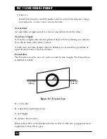
Page 126: ... antenna from the location of the other antenna A radio wave clear line of sight exists if a defined area around the optical line of sight Fresnel Zone is clear of obstacles Fresnel Zone The Fresnel zone is the area of a circle around the line of sight The Fresnel Zone is defined as follows Figure D 7 Fresnel Zone R 1 2 λ D R radius of the first Fresnel zone λ wavelength D distance between sites W...

Page 127: ...Basic Service Set or BSS in the 802 11 nomenclature is controlled by a Base Station called Access Point Although a wireless LAN may be formed by a single cell with a single Access Point and as will be described later it can also work without an Access Point most installations will be formed by several cells where the Access Points are connected through some kind of backbone called Distribution Sys...

Page 128: ...al on a single physical entity For example the Pro 11 Series Access Point provides both functions E 2 IEEE 802 11 Layers Description As in any 802 x protocol the 802 11 protocol covers the Media Access Control Layer MAC and Physical Layer PHY The Standard currently defines a single MAC which interacts with three PHYs all of them running at 1 or 2 Mbps as follows Frequency Hopping Spread Spectrum F...

Page 129: ...e very effective when the medium is not heavily loaded since they allow stations to transmit with minimum delay But there is always a chance of two or more stations simultaneously sensing the medium as being free and transmitting at the same time causing a collision These collision situations must be identified so the packet can be retransmitted by the MAC layer itself not by the upper layers to a...

Page 130: ...he following transaction i e the packet and the respective ACK the destination station responds if the medium is free with a response control packet called CTS Clear to Send which includes the same duration information All stations receiving either the RTS or the CTS set their Virtual Carrier Sense indicator called NAV for Network Allocation Vector for the given duration and use this information t...

Page 131: ...use packets several hundred bytes long the longest Ethernet packet could be up to 1518 bytes long There are several reasons why it is preferable to use smaller packets in a wireless LAN environment Because of the higher Bit Error Rate of a radio link the probability of a packet s getting corrupted increases with the packet size In case of packet corruption due to either collision or noise the smal...

Page 132: ...an ACK for the said fragment or 2 It decides that the fragment was retransmitted too many times and drops the whole frame It should be noted that the standard does allow the station to transmit to a different address between retransmissions of a given fragment This is particularly useful when an Access Point has several outstanding packets to different destinations and one of them does not respond...

Page 133: ... station willing to start a new transmission which is calculated as PIFS plus one slot time i e 128 microseconds EIFS Extended IFS which is a longer IFS used by a station that has received a packet that it could not understand This is needed to prevent the station which could not understand the duration information for the Virtual Carrier Sense from colliding with a future packet belonging to the ...

Page 134: ...fter power up after sleep mode or just entering the BSS area the station needs to get synchronization information from the Access Point or from the other stations when in ad hoc mode which will be discussed later The station can get this information by one of two means 1 Passive Scanning In this case the station just waits to receive a Beacon Frame from the Access Point the beacon frame is a frame...

Page 135: ...rocess of moving from one cell or BSS to another without losing connection This function is similar to the cellular phones handover with two main differences 1 On a packet based LAN system the transition from cell to cell may be performed between packet transmissions as opposed to telephony where the transition may occur during a phone conversation This makes the LAN roaming a little easier but 2 ...

Page 136: ...d cause loss of sync after a few hours of operation E 7 Security Security is one of the first concerns that people have when deploying a wireless LAN The 802 11 committee has addressed the issue by providing what is called WEP Wired Equivalent Privacy Users are primarily concerned that an intruder should not be able to Access the Network resources by using similar wireless LAN equipment Capture wi...

Page 137: ...ving mode and buffers the packets addressed to these stations until either the stations specifically request the packets by sending a polling request or until they change their operation mode As part of its Beacon Frames the Access Point also periodically transmits information about which Power Saving Stations have frames buffered at the Access Point so these stations wake up in order to receive t...

Page 138: ...rames are composed of the following components Preamble PLCP Header MAC Data and CRC E 10 1 PREAMBLE This is PHY dependent and includes Synch An 80 bit sequence of alternating zeros and ones which is used by the PHY circuitry to select the appropriate antenna if diversity is used and to reach steady state frequency offset correction and synchronization with the received packet timing SFD A Start F...

Page 139: ...Frame Control field contains the following information Figure E 6 Frame Control Field Protocol Version This field consists of 2 bits which are unvarying in size and placement across following versions of the 802 11 Standard and will be used to recognize possible future versions In the current version of the standard the value is fixed as 0 Protocol Version B0 2 Bits 2 4 1 1 1 1 1 1 1 1 B1 Type To ...

Page 140: ...ment 0110 0111 Reserved 00 Management 1000 Beacon 00 Management 1001 ATIM 00 Management 1010 Disassociation 00 Management 1011 Authentication 00 Management 1100 Deauthentication 00 Management 1101 1111 Reserved 01 Control 0000 0001 Reserved 01 Control 1010 PS Poll 01 Control 1011 RTS 01 Control 1100 CTS 01 Control 1101 ACK 01 Control 1110 CF End 01 Control 1111 CF End CF ACK 10 Data 0000 Data 10 D...

Page 141: ...t packet is lost Power Management This bit indicates the Power Management mode that the station will be in after the transmission of this frame This is used by stations which are changing state either from Power Save to Active or vice versa More Data This bit is used for Power Management as well as by the Access Point to indicate that there are more frames buffered for this station The station may...

Page 142: ...hysically transmitting the packet If FromDS is set this is the Access Point address if it is not set then it is the station address Address 3 is in most cases the remaining missing address On a frame with FromDS set to 1 Address 3 is the original source address if the frame has the ToDS set then Address 3 is the destination address Address 4 is used in special cases where a Wireless Distribution S...

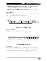
Page 143: ...c Redundancy Check CRC E 11 Most Common Frame Formats E 11 1 RTS FRAME FORMAT The RTS frame looks like this Figure E 7 RTS Frame Format The RA of the RTS frame is the address of the Station Adapter on the wireless medium that is the intended immediate recipient of the next Data or Management frame The TA is the address of the Station Adapter transmitting the RTS frame The Duration value is the tim...

Page 144: ...CTS frame and its SIFS interval E 11 3 ACK FRAME FORMAT The ACK frame looks like this Figure E 9 ACK Frame Format The Receiver Address of the ACK frame is copied from the Address 2 field of the immediately previous frame If the More Fragment bit was set to 0 in the Frame Control field of the previous frame the Duration value is set to 0 otherwise the Duration value is obtained from the Duration fi...

Page 145: ...le regular stations to access the medium there is a provision that the Access Point must leave enough time for Distributed Access in between the PCF E 13 Ad hoc Networks In certain circumstances the users may wish to build up wireless LAN networks without an infrastructure more specifically without an Access Point This may include file transfer between two notebook users coworkers meeting outside ...

Page 146: ...1000 Park Drive Lawrence PA 15055 1018 724 746 5500 Fax 724 746 0746 Copyright 2000 Black Box Corporation All rights reserved ...

Reviews: