3.4.2 V
IA
T
HE
E
THERNET
P
ORT
There are three ways to configure and monitor the switch through the switch’s Ethernet port: CLI, Web
browser, and SNMP management. The user interface for SNMP is NMS dependent and is not described here.
CLI and Web browser interfaces are described below.
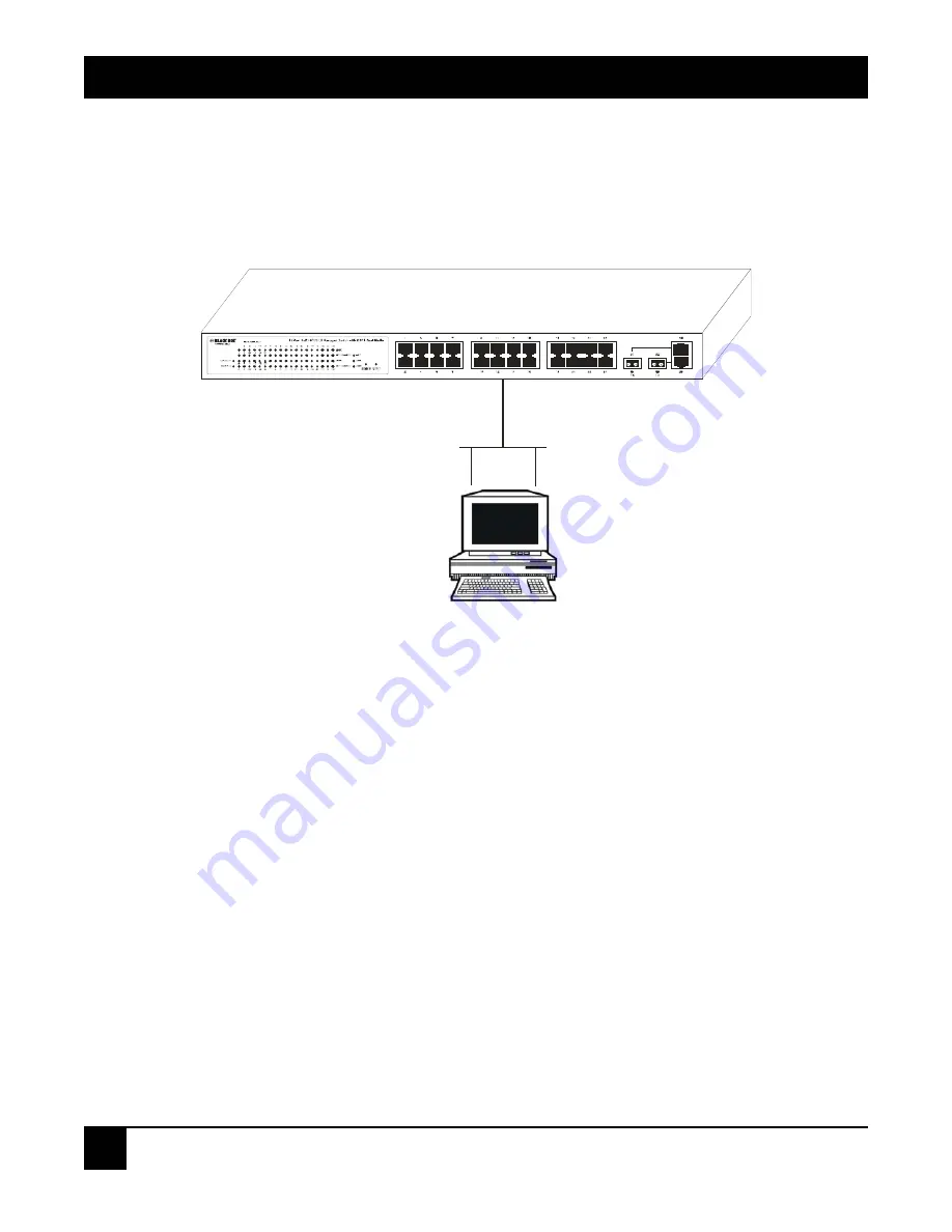
Figure 3-9. Connecting the Ethernet LAN PC to the switch for network management through an
Ethernet port.
Managing the Switch via the Ethernet Port
Before you communicate with the switch, you must first configure or identify the switch’s IP address. Next,
follow the steps listed below.
1. Connect the switch and PC together via UTP CAT5 cable with RJ-45 connectors.
NOTE
If the PC directly connects to the switch, set up the same subnet mask between them.
If the PC connects to the switch through a remote site, the remote PC’s subnet mask
may be different.
2. Run CLI or a Web browser and follow the menus. For details, refer to
Chapters 4
and
5
.
3. A login screen appears. Type in the switch’s username and password in this screen.
24-Port 10/100BASE-TX L2 Managed PoE Switch with 2 SFP Dual Media Ports
Ethernet
LAN
PC
24-Port 10/100BASE-TX L2 Managed PoE
Switch with 2 SFP Dual Media Ports
Assign a reasonable IP address, for
example:
IP address: 192.168.1.100
Subnet mask: 255.255.255.0
Default gateway: 192.168.1.254
24


