10 IIoT functionality
10.1 MQTT
3.
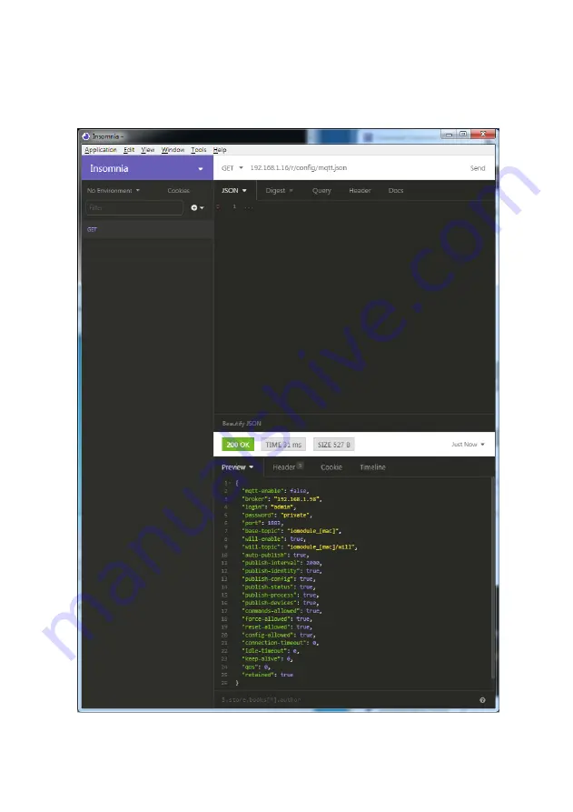
Read MQTT:
GET:
[IP-address]/r/config/mqtt.json
Manual EtherCAT®
Version 1.1 04/2021
103
Page 1: ...IO Link Class A Multiprotocol LioN Xlight IO Link Master 0980 LSL 3211 121 0006 004 8 x IO Link Class A EtherCAT 0980 LSL 3210 121 0006 004 4 x IO Link Class A 8 x DI EtherCAT Manual EtherCAT Version...
Page 2: ...on information 9 2 Safety instructions 10 2 1 Intended use 10 2 2 Qualified personnel 11 3 Designations and synonyms 12 4 System description 15 4 1 About LioN X and LioN Xlight 15 4 2 Device variants...
Page 3: ...as M12 sockets 32 6 3 3 1 IO Link Class A 32 7 Starting operation 34 7 1 ESI file 34 7 2 MAC addresses 35 7 3 Setting the rotary encoding switches 36 7 3 1 Factory reset 38 8 Configuration and operat...
Page 4: ...2 EoE IP address 78 8 3 3 Activate configuration 80 9 Diagnostics processing 81 9 1 Error of the system sensor power supply 81 9 2 Error of the auxiliary actuator power supply 81 9 3 Overload short c...
Page 5: ...configuration via JSON 108 10 3 REST API 110 10 3 1 Standard device information 112 10 3 2 Structure 113 10 3 3 Configuration and forcing 119 10 3 4 Reading and writing ISDU parameters 121 10 3 4 1 R...
Page 6: ...actuators 141 13 5 IO Link Master ports Class A Pin 4 142 13 5 1 Configured as a digital input 142 13 5 2 Configured as a digital output 143 13 5 3 Configured as an IO Link port in COM mode 144 13 6...
Page 7: ...used exclusively to explain how to operate and apply the modules Please contact us if you have any detailed questions on installing and starting up the devices Belden Deutschland GmbH Lumberg Automati...
Page 8: ...physical injury or substantial damage to property can occur if the required safety measures are not taken Caution Means that minor physical injury or damage to property can occur if the required safet...
Page 9: ...herCAT is a registered trademark and patented technology licensed by Beckhoff Automation GmbH Germany 1 3 Version information Index Created Changed Version number Version 1 0 Version 1 1 Date 03 2021...
Page 10: ...dditional measures are required for use in residential areas or in business and commercial sectors Attention This equipment may cause radio interference in residential areas In this case the operator...
Page 11: ...persons who D based on their technical training knowledge and experience and their knowledge of the pertinent standards can evaluate the work to be carried out and identify any potential risks or D ba...
Page 12: ...IO Link port specification Class A Class B IO Link port specification Class B CoAP Constrained Application Protocol DCP Discovery and Configuration Protocol DevCom Device Comunicating EIP diagnostics...
Page 13: ...t X1 X8 I O port pin 2 Channel B of X1 X8 I O port pin 4 C Q Channel A of X1 X8 IOL or IO L IO Link ISDU Indexed Service Data Unit IVE IO Link port Validation Error EIP diagnostics I M Identification...
Page 14: ...onal State Transfer RFC Request for Comments RPI Requested Packet Interval SCA Short Circuit Actuator UL UAux EIP diagnostics SCS Short Circuit Sensor EIP diagnostics SNMP Simple Network Management Pr...
Page 15: ...s which convert standard input standard output or IO Link signals from sensors actuators into an industrial Ethernet protocol PROFINET EtherNet IP EtherCAT Modbus TCP and or into a cloud protocol REST...
Page 16: ...0006 001 LioN Xlight M12 60 mm IO Link Master PROFINET 4 x IO Link Class A 8 x DI 935701002 0980 LSL 3111 121 0006 002 LioN Xlight M12 60 mm IO Link Master EtherNet IP 8 x IO Link Class A 935702002 09...
Page 17: ...Product designation Description I O port functionality 935702003 0980 LSL 3210 121 0006 004 LioN Xlight M12 60 mm IO Link Master EtherCAT 4 x IO Link Class A 8 x DI Table 3 Overview of LioN X and LioN...
Page 18: ...DI DO 0 5 A DO 2 A DI DO 2 A X7 Out 4 A IOL DI DO 0 5 A DO 2 A DI DO 2 A X6 Out 4 A IOL DI DO 0 5 A DO 2 A DI DO 2 A X5 Out 4 A IOL DI DO 0 5 A DO 2 A DI DO 2 A X4 Out 4 A IOL DI DO 0 5 A DO 2 A DI D...
Page 19: ...2 A IOL DI DO 0 5 A DI X6 Out 2 A IOL DI DO 0 5 A DI X5 Out 2 A IOL DI DO 0 5 A DI X4 Out 2 A IOL DI DO 0 5 A DI X3 Out 2 A IOL DI DO 0 5 A DI X2 Out 2 A IOL DI DO 0 5 A DI 0980 LSL 3x11 X1 Out 2 A I...
Page 20: ...7 Out 0 7 A DI DI X6 Out 0 7 A DI DI X5 Out 0 7 A DI DI X4 Out 2 A IOL DI DO 0 5 A DI X3 Out 2 A IOL DI DO 0 5 A DI X2 Out 2 A IOL DI DO 0 5 A DI 0980 LSL 3x10 X1 Out 2 A IOL DI DO 0 5 A DI Table 6 Po...
Page 21: ...nt the ports from being mixed up Data transmission rates Support of 100Mbit s with auto crossover and auto negotiation corresponding to IEEE 802 3 Integrated switch The integrated Ethernet switch with...
Page 22: ...ink port connections The IO Link port connection option provided by LioN X devices is the 5 pin M12 connector Pin 5 is not assigned for IO Link Class A ports Validation Backup The Validation Backup fu...
Page 23: ...sk and gateway Displaying diagnostics View diagnostics via the integrated Web server User management Use the integrated Web server for convenient management of all users IO Link Device parameters You...
Page 24: ...ulated firmware updates User manager The Web server provides a user manager to protect the Web interface against unauthorized access You can manage the allowed users with the different access levels A...
Page 25: ...f a loss of the PLC communication Industrial Internet of Things LioN X is industry 4 0 ready and supports the integration in IIoT networks via REST API and the IIoT relevant protocols MQTT and OPC UA...
Page 26: ...he EMC immunity This is labeled with the symbol for the ground and the designation FE Attention Use a low impedance connection to connect the module to the reference ground When using a grounded mount...
Page 27: ...6 Assembly and wiring 6 2 Outer dimensions 6 2 Outer dimensions 6 2 1 LioN X multiprotocol variants Figure 1 0980 XSL 3912 121 007D 00F Manual EtherCAT Version 1 1 04 2021 27...
Page 28: ...6 2 Outer dimensions 6 Assembly and wiring 6 2 2 LioN Xlight variants with EtherCAT Figure 2 0980 LSL 3211 121 0006 004 Manual EtherCAT Version 1 1 04 2021 28...
Page 29: ...6 Assembly and wiring 6 2 Outer dimensions Figure 3 0980 LSL 3210 121 0006 004 Manual EtherCAT Version 1 1 04 2021 29...
Page 30: ...ion of 2000 meters Approved up to a maximum soiling level of 2 Warning Terminals housings field wired terminal boxes or components can exceed temperatures of 60 C 140 F Warning For UL application max...
Page 31: ...ve data minus Table 7 Assignment of ports X01 X02 Caution Risk of destruction Never connect the power supply to the data cables 6 3 2 Power supply with M12 power L coded Color coding gray Figure 5 Sch...
Page 32: ...M12 Power Attention Only use power supply units for the system sensor and actuator supply that correspond to PELV Protective Extra Low Voltage or SELV Safety Extra Low Voltage Power supplies accordin...
Page 33: ...IN OUT Ch A IO Link data communication digital input or digital output IO Link Class A ports X1 X8 5 n c not connected 0980 LSL 3x10 121 Pin Signal Function 1 24 V power supply 24 V 2 IN Ch B Digital...
Page 34: ...d LumbergAutomation LioN X IO Link Master xml Download this file and unpack it Install the ESI file for the device variant used via the hardware or network configuration tool of your controller manufa...
Page 35: ...ress assigned by the manufacturer that cannot be changed by the user The first assigned MAC address is printed onto the device For EtherCAT the MAC address has no function For EoE Ethernet over EtherC...
Page 36: ...evices you can easily and conveniently set both the protocol and the address of the device if the protocol to be used supports this Once you have made a protocol selection and started the cyclical com...
Page 37: ...g a power cycle or Reset from the Web interface is necessary Once you have set the protocol using the rotary encoding switches the device stores this setting when it starts in cyclic communication Cha...
Page 38: ...power cycle and wait 10 seconds due to internal memory write processes During the factory reset the US LED is blinking red After the internal memory write processes have finished the US LED returns t...
Page 39: ...put and output data By selecting the relevant PDO you can decide your preferred I O data content The devices feature a dynamic slot based PDO assignment The following PDO assignments are provided 8 1...
Page 40: ...byte of IO Link input data PDO 0x1A02 PDO PDO content Index Size Index Size Type Name 0x6020 1 1 UINT32 1st byte of IO Link input data 0x1A02 32 0x6020 32 1 UINT32 32nd byte of IO Link input data PDO...
Page 41: ...byte of IO Link input data PDO 0x1A05 PDO PDO content Index Size Index Size Type Name 0x6050 1 1 UINT32 1st byte of IO Link input data 0x1A05 32 0x6050 32 1 UINT32 32nd byte of IO Link input data PDO...
Page 42: ...1 UINT32 32nd byte of IO Link input data PDO 0x1A08 PDO PDO content Index Size Index Size Type Name 0x2080 1 1 UINT32 Digital input status of ports X1 X4 Bitwise 0x2080 2 1 UINT32 Digital input status...
Page 43: ...PDO content Index Size Index Size Type Name 0x1A09 1 0x10F3 4 1 UINT32 Flag New Messages Available from Diagnostic Object 0x10F3 PDO 0x1A0A PDO PDO content Index Size Index Size Type Name 0x1A0A 1 0x1...
Page 44: ...s IO Link port 1 0xF100 2 1 UINT32 Status IO Link port 2 0xF100 3 1 UINT32 Status IO Link port 3 0xF100 4 1 UINT32 Status IO Link port 4 0xF100 5 1 UINT32 Status IO Link port 5 0xF100 6 1 UINT32 Statu...
Page 45: ...ype Name 0x7000 1 1 UINT32 1st byte of IO Link output data 0x1A00 32 0x7000 32 1 UINT32 32nd byte of IO Link output data PDO 0x1601 PDO PDO content Index Size Index Size Type Name 0x7010 1 1 UINT32 1s...
Page 46: ...yte of IO Link output data PDO 0x1603 PDO PDO content Index Size Index Size Type Name 0x7030 1 1 UINT32 1st byte of IO Link output data 0x1A03 32 0x7030 32 1 UINT32 32nd byte of IO Link output data PD...
Page 47: ...yte of IO Link output data PDO 0x1606 PDO PDO content Index Size Index Size Type Name 0x7060 1 1 UINT32 1st byte of IO Link output data 0x1606 32 0x7060 32 1 UINT32 32nd byte of IO Link output data PD...
Page 48: ...x Size Index Size Type Name 0x2280 1 1 UINT32 Digital output mapping for ports X1 X4 Bitwise 0x2280 2 1 UINTtwincat32 Digital output mapping for ports X5 X8 Bitwise 0x2280 3 1 UINT32 Control of IO Lin...
Page 49: ...I_16byte IO Link 16 bytes of process data input IOL_I_24byte IO Link 24 bytes of process data input IOL_I_32byte IO Link 32 bytes of process data input STD_OUT_1_bit IO Link port as standard Digital O...
Page 50: ...O_2 8byte IO Link 2 bytes of process data input 8 bytes of process data output IOL_I O_4 8byte IO Link 4 bytes of process data input 8 bytes of process data output IOL_I O_8 2byte IO Link 8 bytes of p...
Page 51: ...16byte IO Link 16 bytes of process data input 16 bytes of process data output IOL_I O_24 24byte IO Link 24 bytes of process data input 24 bytes of process data output IOL_I O_32 32byte IO Link 32 byt...
Page 52: ...DO SDO content Index Size Index Size Type Name specification 0x23n0 1 1 UINT8 Data Storage 0 Data Storage disabled stored data set is preserved 1 Data Storage download only IOLM IOLD 2 Data Storage up...
Page 53: ...e the option to define the replacement value of the IO Link output data The following table represents failsafe replacement values of IO Link output data while the port is in IO Link mode SDO SDO cont...
Page 54: ...ents possible failsafe replacement values of ports in digital output mode The following options are available Set low default value Deactivate the output channel value 0 Set high Activate the output c...
Page 55: ...80 6 1 UINT8 Port 3 Channel B 0 Set Low 1 Set High 2 Hold Last Others reserved 0x2380 7 1 UINT8 Port 4 Channel A 0 Set Low 1 Set High 2 Hold Last Others reserved 0x2380 8 1 UINT8 Port 4 Channel B 0 Se...
Page 56: ...Set High 2 Hold Last Others reserved 0x2380 13 1 UINT8 Port 7 Channel A 0 Set Low 1 Set High 2 Hold Last Others reserved 0x2380 14 1 UINT8 Port 7 Channel B 0 Set Low 1 Set High 2 Hold Last Others rese...
Page 57: ...2381 1 1 BOOL Web Interface Locked 0 false 1 true 0x2381 2 1 BOOL Force Mode Locked 0x2381 3 1 BOOL Disable All Emergency Messages 0 false 1 true 0x2381 4 1 BOOL Disable UL Emergency Messages 0 false...
Page 58: ...will report error states The value of the surveillance timeout is 0 to 255ms The default value is 80ms While an output channel is in static state permanently switched on or off the respective value i...
Page 59: ...hannel B 0x2382 11 1 UINT8 Surveillance TimeoutPort 6 Channel A 0x2382 12 1 UINT8 Surveillance Timeout Port 6 Channel B 0x2382 13 1 UINT8 Surveillance Timeout Port 7 Channel A 0x2382 14 1 UINT8 Survei...
Page 60: ...383 2 1 UINT8 Digital I O Mode Port 2 Channel B 1 Input 2 Output Others reserved 0x2383 3 1 UINT8 Digital I O Mode Port 3 Channel B 1 Input 2 Output Others reserved 0x2383 4 1 UINT8 Digital I O Mode P...
Page 61: ...Configuration and operation in TwinCAT 3 8 2 Device parameters SDO SDO content 0x2383 8 1 UINT8 Digital I O Mode Port 8 Channel B 1 Input 2 Output Others reserved Manual EtherCAT Version 1 1 04 2021 6...
Page 62: ...ex Size Type Name 0x2384 1 1 UINT8 Digital Input logic Port 1 Channel A 0 NO 1 NC 0x2384 2 1 UINT8 Digital Input logic Port 1 Channel B 0 NO 1 NC 0x2384 3 1 UINT8 Digital Input logic Port 2 Channel A...
Page 63: ...5 Channel B 0 NO 1 NC 0x2384 11 1 UINT8 Digital Input logic Port 6 Channel A 0 NO 1 NC 0x2384 12 1 UINT8 Digital Input logic Port 6 Channel B 0 NO 1 NC 0x2384 13 1 UINT8 Digital Input logic Port 7 Ch...
Page 64: ...ter Port 2 Channel B 0x2385 5 1 UINT8 Digital Input Filter Port 3 Channel A 0x2385 6 1 UINT8 Digital Input Filter Port 3 Channel B 0x2385 7 1 UINT8 Digital Input Filter Port 4 Channel A 0x2385 8 1 UIN...
Page 65: ...Digital output timeout before restart in ms Port 2 Channel A 0x2386 4 1 BOOL Digital output timeout before restart in ms Port 2 Channel B 0x2386 5 1 BOOL Digital output timeout before restart in ms Po...
Page 66: ...l B 0x2386 13 1 BOOL Digital output timeout before restart in ms Port 7 Channel A 0x2386 14 1 BOOL Digital output timeout before restart in ms Port 7 Channel B 0x2386 15 1 BOOL Digital output timeout...
Page 67: ...d 0 false 1 true 0x30n0 6 1 BOOL Supress All Diagnosis 0 false 1 true 0x30n0 7 1 BOOL Pin 4 DO use of Push Pull 0 Use High Side switches 1 Use Push Pull 0x30n0 8 1 UINT16 Pin 4 current limit in mA Max...
Page 68: ...ytes or DWord 4 Bytes Word Swapping Byte 1 Byte 2 Byte 2 Byte 1 DWord Swapping Byte 1 Byte 4 Byte 4 Byte 1 Swapping Offset A swapping offset in bytes can be setup in dependency of the configured I O D...
Page 69: ...Index Size Index Size Type Name 0x40n0 1 1 UINT8 Control 0x00 no action 0x02 write 0x03 read 0x40n0 2 1 UINT8 Status 0x00 no activity 0x01 active busy 0x02 access 0x04 error 0xFF failure 0x40n0 3 1 UI...
Page 70: ...Offset Time 0x80n0 36 1 UINT8 Process data IN length Number and structure of input data This value is transmitted in IO Link format as ProcessDataIn according to version 1 0 of the IO Link specificati...
Page 71: ...Inactive 1 Digital Input Port 2 Digital Output Port 3 Communication over IO Link Protocol 4 Digital input with support for acyclic IO Link Key n number between 0 7 port number 1 8 2 13 IO Link serial...
Page 72: ...device according to version 1 0 of the IO Link specification Bit 0 3 Minor Rev Bit 4 7 Major Rev 0x90n0 33 1 UINT8 Frame Capability 0x90n0 34 1 UINT8 Cycle Time 0x90n0 35 1 UINT8 Offset Time 0x90n0 7...
Page 73: ...icator if device supports standard I O mode Bit 7 Byte Indicator if value of length is interpreted as bit length or as byte length 1 Key n number between 0 7 port number 1 8 2 15 IO Link serial number...
Page 74: ...ice family in TwinCAT For TwinCAT the ESI file must be copied into the installation folder e g C TwinCAT 3 1 Config Io EtherCAT 2 After installation TwinCAT needs a system restart Alternatively use th...
Page 75: ...T 3 5 If not already done choose the network adapter and install the driver for EtherCAT real time communication Browse to Adapter in the right workspace window and click on Compatible Devices to choo...
Page 76: ...erCAT and choose the option Add New Item Select the device and click on OK 2 Configuring the Slots Browse to Slots in the right workspace window and configure the IO Link channels You can change for e...
Page 77: ...ation in TwinCAT 3 8 3 Configuration example with TwinCAT 3 3 Configure the Process Data Browse to Process Data in the right workspace window and choose the PDOs for Inputs and Outputs Manual EtherCAT...
Page 78: ...ress for the EoE Ethernet over EtherCAT protocol For using the Web interface of the device the IP address must be set Click on EtherCAT Advanced Settings in the right workspace window and navigate to...
Page 79: ...on in TwinCAT 3 8 3 Configuration example with TwinCAT 3 3 Activate IP Port and IP Address when using Web services Enter your IP settings depending from your local network adapter settings Manual Ethe...
Page 80: ...the device 1 When the device is connected to the EtherCAT network click on TwinCAT in the top ribbon and choose Activate Configuration in the upcoming window 2 Click again on TwinCAT in the top ribbo...
Page 81: ...9 2 Error of the auxiliary actuator power supply The voltage value for the incoming auxiliary actuator power supply is also monitored globally If UAux diagnostic messaging is enabled an error message...
Page 82: ...ter can range from 0 to 255 ms the factory setting is 80 ms The filter is used to avoid premature error messages when a capacitive load is activated or an inductive load is deactivated and during othe...
Page 83: ...imum Messages Number of diagnosis messages which can be stored in the diagnosis history subindex 6 onwards 9 6 2 Newest Message Sub index of the newest diagnosis message 6 69 9 6 3 Newest Acknowledge...
Page 84: ...g 69 255 The slave returns SDO abort with code 0x06090031 value of parameter written too high Acknowledge mode SI5 bit 4 1 Read 0 No messages have been acknowledged so far Read 0 Sub index of latest a...
Page 85: ...t message was not read Acknowledge mode 0 no unacknowledged message 1 diagnosis messages are available which can be acknowledged SI2 SI3 9 6 5 Flags Flags to control sending and storing of diagnosis m...
Page 86: ...s do only overwrite messages which were acknowledged before Bit 5 Overwrite Discard Information read only In Overwrite mode 1 Unacknowledged messages have been overwritten buffer overrun SI3 is set to...
Page 87: ...2 0xA0n0 2 1 UINT8 Lost Frames IO Link State State of the IO Link Master state machine of the IO Link port 0x0 Port inactive 0x01 Digital input 0x02 Digital output 0x03 Establish communication 0x04 0...
Page 88: ...100 4 1 UINT8 Status Port 4 0xF100 5 1 UINT8 Status Port 5 0xF100 6 1 UINT8 Status Port 6 0xF100 7 1 UINT8 Status Port 7 0xF100 8 0xF100 8 1 UINT8 Status Port 8 Status Ports 1 8 Status of the IO Link...
Page 89: ...osis on the Device Emergency error code B7 B6 B5 B4 B3 B2 B1 B0 Error description 0x0000 0 0 0 0 0 0 0 0 No error 0x2300 0 0 0 0 0 1 1 Sensor short circuit 0x3100 0 0 0 0 1 1 US Voltage error 0x3300 0...
Page 90: ...ion in a LioN X device can be read They also enable its configuration and control if the user wishes All interfaces can be configured extensively and offer read only functionality All LioN X variants...
Page 91: ...occur periodically or be triggered manually 10 1 1 MQTT configuration The MQTT client can be configured either using the Web interface or directly via a JSON object sent in an HTTP request For more i...
Page 92: ...ed Minimum is 250 ms 1000 publish identity boolean If true all identity domain data will be published true false publish config boolean If true all config domain data will be published true false publ...
Page 93: ...object for each error occurred The object consists of a field Element which names the config element which caused the error and a field Message for the error message D A malformed JSON object produce...
Page 94: ...he Base topic can also contain selected variables as shown in Table 12 Base topic variables on page 94 Variables in the Base topic have to be written in brackets The following variables are possible V...
Page 95: ...diagnostic information IO Link device status and data process All process data which is produced and consumed by the device itself or by attached devices Digital inputs digital outputs cyclic IO Link...
Page 96: ...gital IN OUT 1 Interval base topic process port n Digital IN OUT per port IOL data pdValid 8 Interval base topic iold port n IO Link device parameter 8 Interval Table 14 Data model An MQTT client whic...
Page 97: ...string mac_address json_string production_date json_string fw_name json_string fw_date json_string fw_version json_string hw_version json_string vendor_name json_string vendor_address json_string vend...
Page 98: ...ing 192 168 1 1 subnet_mask json_string 255 255 255 0 report_alarms json_boolean 0 0 0 0 report_ul_alarm json_boolean true false true report_do_fault_without_ul json_boolean true false false force_mod...
Page 99: ...t s_full 100_mbit s module_restarts json_integer 0 4294967295 channel_diagnosis json_boolean true false failsafe_active json_boolean true false system_voltage_fault json_boolean true false actuator_vo...
Page 100: ...rsal digital_input digital_Output io_link max_output_power_cha json_string 2 0_mA 0 5_mA max_output_power_chb json_string 2 0_mA 0 5_mA channel_cha json_string input output input output io_link aux ch...
Page 101: ...set_high hold_last set_low surveillance_timeout_cha json_integer 0 255 80 surveillance_timeout_chb json_integer 0 255 80 Table 21 Config port 1 8 Key Data type Range Default value Remarks port json_in...
Page 102: ...ferenced Web pages and provides no warranty for any functionality of the named third party software 10 1 3 1 MQTT configuration via JSON 1 Depending on your application case download and install Insom...
Page 103: ...10 IIoT functionality 10 1 MQTT 3 Read MQTT GET IP address r config mqtt json Manual EtherCAT Version 1 1 04 2021 103...
Page 104: ...lient server principle and lets machines and devices regardless of any preferred field bus communicate horizontally among each other as well as vertically to the ERP system or the cloud LioN X provide...
Page 105: ...chapter 8 3 in the specification Not supported Table 23 Non supported OPC UA features according to the IO Link Companion Specification 10 2 1 OPC UA configuration The OPC UA Server can be configured e...
Page 106: ...nges via OPC UA true false Table 24 OPC UA Configration All configuration elements are optional and do not need a specific order Not every element is required to be sent This means that only configura...
Page 107: ...established via the endpoint URL opc tcp ip address port Various device data such as MAC address device settings diagnostics or status information can be read via Identity objects Config objects Statu...
Page 108: ...erenced Web pages and provides no warranty for any functionality of the named third party software 10 2 3 1 OPC UA configuration via JSON 1 Depending on your application case download and install Inso...
Page 109: ...10 IIoT functionality 10 2 OPC UA 3 Read OPC UA GET IP address r config opcua json Manual EtherCAT Version 1 1 04 2021 109...
Page 110: ...rent REST API standards you can use for the requests 1 A standardized REST API that has been specified by the IO Link Community and is described separately JSON_Integration_10222_V100_Mar20 pdf Please...
Page 111: ...rameters Yes GET parameters index subindices Yes GET parameters parameterName subindices Not supported GET parameters index value Yes GET parameters index subindices subindex value Yes GET parameters...
Page 112: ...A customized Belden REST API that is described in the following chapters 10 3 1 Standard device information Request method http GET Request URL ip info json Parameters n a Response format JSON The goa...
Page 113: ...teway rotarys array of numbers 3 Current position of the rotary switches Array element 0 x1 Array element 1 x10 Array element 2 x100 ulPresent boolean True if there is a UL voltage supply detected wit...
Page 114: ...Element 2 1 Byte Actuator short circuit ports X1 Channel A X4 Channel B diag array of numbers 4 Diagnostic information Element 3 1 Byte Actuator short circuit ports X5 Channel A X8 Channel B fieldbus...
Page 115: ...ports array of PORT 8 Contains one element for each IO Link port CHANNEL Object name string Name of channel type number Hardware channel type as number 0 DIO 1 Input 2 Output 3 Input Output 4 IO Link...
Page 116: ...red current of the output in mA if current measurement is available voltage_mV number Measured voltage of this output in mV if voltage measurement is available PORT Object port_type string Textual rep...
Page 117: ...code according to IO Link specification eventqualifier number Event qualifier according to IO Link specification message string Error message Supply Voltage fault DEVICE Object Standard parameters of...
Page 118: ...REST API at the moment forcingClient string Current forcing client identifier digitalOutForced array of numbers 2 The force values of all 16 digital output channels digitalOutMask array of numbers 2...
Page 119: ...uthority on off portmode array Port mode object digital array Digital object iol array IOL object Table 26 Root object Property Data type Example values Remarks port integer 0 7 channel integer a b op...
Page 120: ...lear optional default is phys_out force_value integer 0 1 Table 28 Digital object Property Data type Example values Remarks port integer 0 7 output array integer or null to clear forcing 55 88 120 Out...
Page 121: ...a single request 10 3 4 1 Reading ISDU Method POST URL ip r isdu json Parameters port 0 7 Example 192 168 1 20 r isdu json port 5 Post Body JSON array of read ISDU object Property Data type Example va...
Page 122: ...16 Index that was read subix integer 0 INT8 Subindex that was read status integer 0 1 0 no error 1 an error occured eventcode integer IOL eventcode if status is 1 data array integer data if no error o...
Page 123: ...subix integer 0 INT8 Subindex to be read data array integer Data to be written Table 33 Write ISDU object Response Write ISDU response object Property Data type Example values Remarks status integer 0...
Page 124: ...es Remarks ix integer 0 INT16 Index that was written subix integer 0 INT8 Subindex that was written status integer 0 1 0 no error 1 an error occured eventcode integer IOL eventcode if status is 1 Tabl...
Page 125: ...7 76 65 54 44 50 48 48 45 77 49 50 status 0 ix 19 subix 0 data 53 48 49 50 57 53 51 53 status 0 ix 20 subix 0 data 100 105 115 116 97 110 99 101 32 115 101 110 115 111 114 status 0 status 0 10 3 6 Exa...
Page 126: ...a Web interface The Web interface provides an overview of the configuration and status of the device It is also possible to use the Web interface to trigger a reboot reset to the factory defaults or...
Page 127: ...of the current state of the device The left side shows a graphical representation of the module with all its LEDs and the positions of the rotary encoding switches The right side shows the Device Inf...
Page 128: ...of the I O ports 11 1 2 The Ports page The page shows detailed port information In the field Port Diagnosis incoming and outgoing diagnostics are displayed as clear text Pin 2 and Pin 4 contain infor...
Page 129: ...ule like Firmware version Device information Ethernet Network and Fieldbus information Restart Device The module initializes a software reset Reset to Factory Settings The module restores to the defau...
Page 130: ...ts the IP address at start up by detecting the PROFINET module via its device name Firmware Update The module initializes a Firmware update For a firmware update choose the ZIP container available on...
Page 131: ...the user management of the Web interface New users with access rights Admin or Write can be added here For security reasons please change the default admin password immediately after configuring the...
Page 132: ...e System page shows the basic information for the module like Firmware version Device information Ethernet Network and Fieldbus information Restart Device The module initializes a software reset Reset...
Page 133: ...ng commissioning Normally the PLC sets the IP address at start up by detecting the PROFINET module via its device name Firmware Update The module initializes a Firmware update For a firmware update ch...
Page 134: ...ne movements D Do NOT interrupt the power supply to the device during the update 12 1 Firmware update via FoE The FoE service must be supported by the IOL Master and the IOL Device The FoE service on...
Page 135: ...In TwinCAT select the device you want to update 3 In the device window on the right go to the box File Access over EtherCAT and press Download 4 In the following window select the update file provided...
Page 136: ...g if not visible 5 Press OK and wait until the file has been transferred to the device Attention After the file has been transferred the device will reset automatically During the restart older firmwa...
Page 137: ...of the most important functional data needed to operate the device For further information and detailed technical data see the respective Data Sheet of your required product in the product specific d...
Page 138: ...oisture max 98 RH for UL certification max 80 RH Housing material Die cast zinc Surface finish frosted nickel Flammability class UL 94 IEC 61010 Vibration resistance oscillation DIN EN 60068 2 6 2008...
Page 139: ...ing Fixed addressing Min cycle time 1 ms Vendor ID 16AH Device ID 0x0400 same for all LioN X devices Mailbox protocols CanOpen over EtherCAT CoE File access over EtherCAT FoE Ethernet over EtherCAT Eo...
Page 140: ...max 4 A per port at Tambient 30 C 0980 LSL 3x11 121 Port X1 X8 Pin 1 max 2 A per port at Tambient 30 C Port X1 X4 L Pin 1 max 2 A per port at Tambient 30 C Current consumption sensor system L Pin 1 0...
Page 141: ...Max 5 Power supply interruption Max 10 ms Reverse polarity protection Yes Operational indicator UL LED green 18 V 1 V UL LED red UL 18 V 1 V or UL 30 V 1 V if Report UL supply voltage fault is enable...
Page 142: ...0980 LSL 3x11 121 Type 1 as per IEC 61131 2 X1 X4 Type 1 as per IEC 61131 2 Input connection 0980 LSL 3x10 121 X5 X8 Type 1 as per IEC 61131 2 Nominal input voltage 24 V DC Input current Typically 3...
Page 143: ...device 0980 LSL 3x10 121 2 A 0980 XSL 3912 121 2 A 0980 LSL 3x11 121 Max output current per channel 3 0980 LSL 3x10 121 0 5 A power supplied via US Short circuit overload protected yes yes Behavior in...
Page 144: ...e IO Link Master specification v1 1 3 ready IEC 61131 9 Communication rates 4 8 kbaud COM 1 38 4 kbaud COM 2 230 4 kbaud COM 3 Line lengths in the IO Link Device max 20 m Number of IO Link ports 8 Min...
Page 145: ...SL 3x11 121 Type 1 as per IEC 61131 2 X1 X4 Type 1 as per IEC 61131 2 Input connection 0980 LSL 3x10 121 X5 X8 Type 1 as per IEC 61131 2 Nominal input voltage 24 V DC Input current Typically 3 mA Chan...
Page 146: ...ent per device 0980 LSL 3x10 121 2 A 0980 XSL 3912 121 2 A 0980 LSL 3x11 121 Max output current per channel 4 0980 LSL 3x10 121 0 A no outputs Short circuit overload protected yes yes Behavior in case...
Page 147: ...sts Flashing green IO Link COM Mode No IO Link communication Yellow Standard IO Mode Status of digital input or output on C Q pin 4 line on X1 X8 A off None of the above conditions White Status of dig...
Page 148: ...controller has established an active connection to the device Red EtherCAT module diagnostic alarm active Red flashing at 1 Hz Watchdog time out fail safe mode is active Red flashing at 2 Hz 3 sec DC...
Page 149: ...14 Accessories 14 Accessories In order to get access to various types of accessories please visit our Web page http www beldensolutions com Manual EtherCAT Version 1 1 04 2021 149...
Page 150: ...300 V1 1 1 ETG 2015 07 5 EtherCAT Slave Information Specification ETG 2000 V1 0 10 ETG 2018 02 6 EtherCAT Modular Device Profile Part 1 General MDP Device Model ETG 5001 1 V0 9 0 ETG 2016 07 7 EtherCA...