


Commissioning
EL34xx
98
Version: 1.5
6.2.3
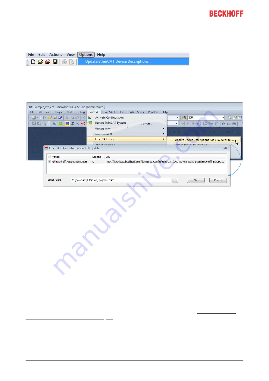
TwinCAT ESI Updater
For TwinCAT 2.11 and higher, the System Manager can search for current Beckhoff ESI files automatically, if
an online connection is available:
Fig. 94:
Using the ESI Updater (>= TwinCAT 2.11)
The call up takes place under:
“Options” → "Update EtherCAT Device Descriptions"
Selection under TwinCAT 3:
Fig. 95:
Using the ESI Updater (TwinCAT 3)
The ESI Updater (TwinCAT 3) is a convenient option for automatic downloading of ESI data provided by
EtherCAT manufacturers via the Internet into the TwinCAT directory (ESI = EtherCAT slave information).
TwinCAT accesses the central ESI ULR directory list stored at ETG; the entries can then be viewed in the
Updater dialog, although they cannot be changed there.
The call up takes place under:
“TwinCAT“ → „EtherCAT Devices“ → “Update Device Description (via ETG Website)…“.
6.2.4
Distinction between Online and Offline
The distinction between online and offline refers to the presence of the actual I/O environment (drives,
terminals, EJ-modules). If the configuration is to be prepared in advance of the system configuration as a
programming system, e.g. on a laptop, this is only possible in “Offline configuration” mode. In this case all
components have to be entered manually in the configuration, e.g. based on the electrical design.
If the designed control system is already connected to the EtherCAT system and all components are
energised and the infrastructure is ready for operation, the TwinCAT configuration can simply be generated
through “scanning” from the runtime system. This is referred to as online configuration.
In any case, during each startup the EtherCAT master checks whether the slaves it finds match the
configuration. This test can be parameterised in the extended slave settings. Refer to
the latest ESI-XML device description” [
.
For preparation of a configuration:
• the real EtherCAT hardware (devices, couplers, drives) must be present and installed
• the devices/modules must be connected via EtherCAT cables or in the terminal/ module strand in the
same way as they are intended to be used later
Summary of Contents for EL34 Series
Page 2: ......
Page 52: ...Mounting and wiring EL34xx 52 Version 1 5 Fig 35 Other installation positions ...
Page 58: ...Mounting and wiring EL34xx 58 Version 1 5 EL3453 LEDs and connection Fig 40 EL3453 LED s ...
Page 92: ...Commissioning EL34xx 92 Version 1 5 Fig 86 Incorrect driver settings for the Ethernet port ...
Page 130: ...Commissioning EL34xx 130 Version 1 5 Fig 147 Process Data tab SM3 EL3443 ...
Page 131: ...Commissioning EL34xx 131 Version 1 5 Fig 148 Process Data tab SM3 EL3453 ...
Page 132: ...Commissioning EL34xx 132 Version 1 5 Fig 149 Process Data tab SM3 EL3483 ...
Page 160: ...Commissioning EL34xx 160 Version 1 5 Index F802 PMX Guard Settings ...
Page 183: ...Commissioning EL34xx 183 Version 1 5 Index F802 PMX Guard Settings ...
Page 205: ...Commissioning EL34xx 205 Version 1 5 Index 1C13 TxPDO assign ...
Page 214: ...Commissioning EL34xx 214 Version 1 5 Index F802 PMX Guard Settings ...
Page 242: ...Commissioning EL34xx 242 Version 1 5 Index 1C13 TxPDO assign ...
Page 259: ...Application examples EL34xx 259 Version 1 5 7 Application examples ...


