background image

Programming

CX8050, CX8051 - Embedded-PCs for

CANopen and CAN

50

Version: 1.4

7

Programming

7.1

Library for CX80xx

Download 

: https://infosys.beckhoff.com/content/1033/cx805x_hw/Resources/zip/1608565003.zip

7.2

Seconds UPS

7.2.1

Function blocks

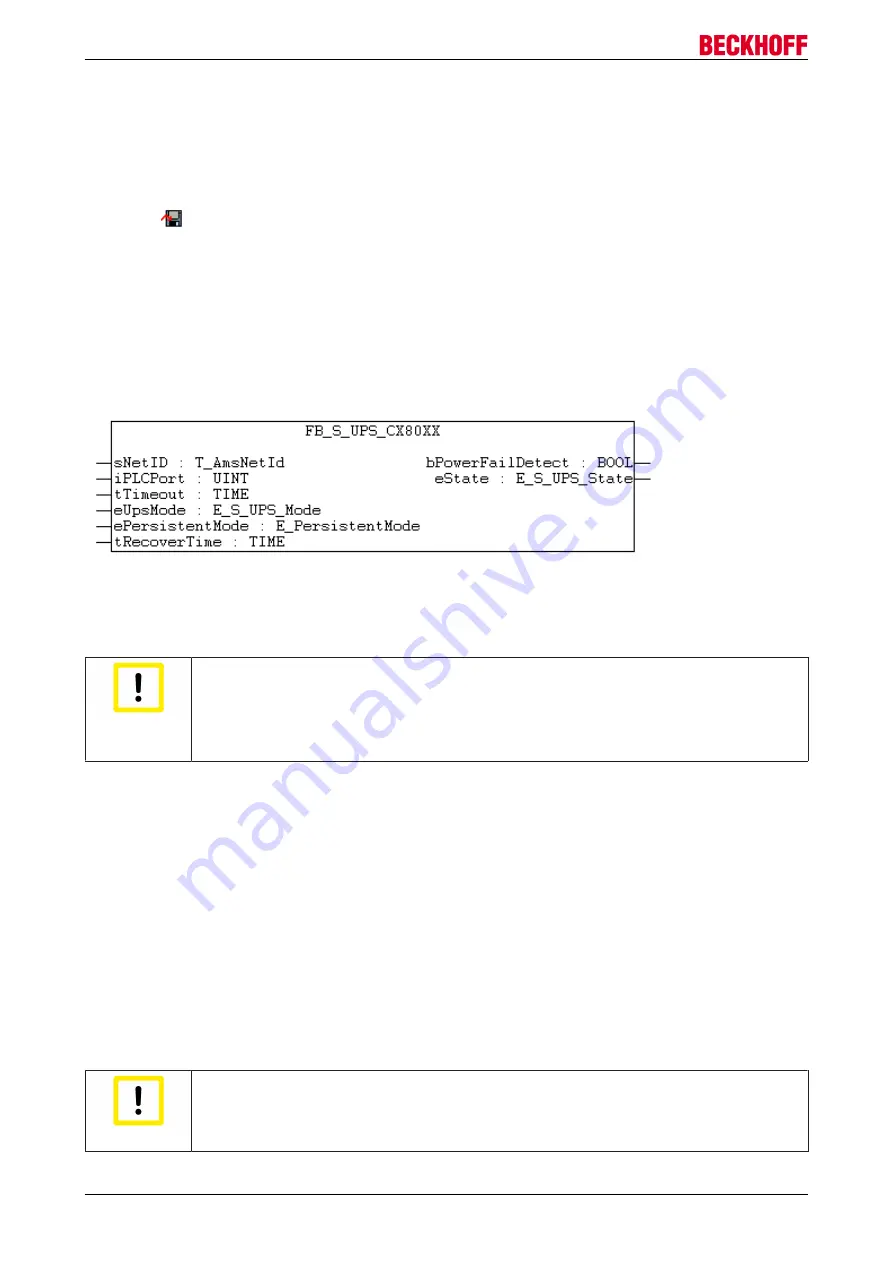
FUNCTION_BLOCK FB_S_UPS_CX80xx

The FB_S_UPS function block can be used on the CX80xx with the seconds UPS in order to activate the
seconds UPS from the PLC. This allows the persistent data to be saved and a quick shutdown to be
performed in the event of a power failure. If possible the default values of the INPUTs of the FB_S_UPS
should be retained.

Attention

Loss of data

The seconds UPS can be used only for a few seconds in the event of a power failure in or-
der, for example, to save persistent data. The data must be saved in the fast persistent
mode "SPDM_2PASS", even though this can lead to real-time violations. Sufficient router
memory must be configured for the storage of the persistent data!

The second UPS does not have sufficient capacity for bridging power failures. Saving can take place only on
Micro SD cards.

A QuickShutdown is performed automatically in the eSUPS_WrPersistData_Shutdown mode (standard
setting) after the storage of the persistent data.

In the eSUPS_WrPersistData_NoShutdown mode only the persistent data are saved, no QuickShutdown is
performed.

In the eSUPS_ImmediateShutdown mode a QuickShutdown is executed immediately without saving data.

In the eSUPS_CheckPowerStatus mode only a check is performed as to whether a power failure has
occurred. If this is the case, the module only switches back to the PowerOK state after the expiry of
tRecoverTime (10s).

Independent of the mode and thus independent of the saving or the shutting down of the controller, the UPS
switches the main board off after the capacitors have discharged, even if the voltage has returned in the
meantime.

Attention

Caution when using files:

If other applications or the PLC keep other files open or write to them, this can lead to faulty
files if the UPS switches off the controller.

Summary of Contents for CX8050

Page 1: ...Documentation for CX8050 CX8051 Embedded PCs for CANopen and CAN CX8050 CANopen Master oder CAN Master CX8051 CANopen Slave 1 4 2018 02 09 Version Date...

Page 2: ......

Page 3: ...nstallation on mounting rails 19 5 2 Wiring 22 5 2 1 Power supply 22 5 2 2 Ethernet 24 5 2 3 CANopen Cabling 26 5 3 Changing the battery 32 6 Parameterization and commissioning 33 6 1 DIP switch 33 6...

Page 4: ...on 67 9 2 1 Network Management 67 9 2 2 Process Data Objects PDO 71 9 2 3 PDO Parameterization 78 9 2 4 Service Data Objects SDO 80 9 3 Objekt dictionary 83 9 3 1 Object Directory Structure 83 9 3 2 O...

Page 5: ...basis of the data diagrams and descriptions in this documentation Trademarks Beckhoff TwinCAT EtherCAT Safety over EtherCAT TwinSAFE XFC and XTS are registered trademarks of and licensed by Beckhoff...

Page 6: ...of death or serious injury WARNING Risk of injury Note this warning Hazard with medium risk of death or serious injury CAUTION Personal injuries Note this warning Hazard with a low degree of risk whi...

Page 7: ...Chapter 1 second UPS added Chapter Operating System added 1 1 Foreword reworked Chapter For your safety added ATEX warnings added 1 2 Chapter Transport and storage added 1 3 Chapter FCC added 1 4 War...

Page 8: ...n objects up to 12 5 mm in size but not protection against water Operation in wet and dusty environments is not permitted unless specified otherwise The specified limits for electrical and technical d...

Page 9: ...an 80 C at the wire branching points cables must be selected that are designed for these high temperatures and operation in potentially explosive atmospheres Tighten the screws of the fieldbus plug co...

Page 10: ...swords Install the devices behind a firewall Apply the IT security precautions according to IEC 62443 in order to limit access to and control of devices and networks Working with the software Use up t...

Page 11: ...n the Embedded PC Despite the robust design of the unit the components are sensitive to strong vibrations and impacts During transport the Embedded PC must be protected from mechanical stress and use...

Page 12: ...of the Embedded PCs have further Ethernet interfaces with switch functions so that a linear daisy chain topology can be constructed inexpensively without additional hardware The other connections on t...

Page 13: ...III Slave Programming The CX80xx controller is programmed according to the high performance IEC 61131 3 standard As with all other Beckhoff controllers the TwinCAT automation software is the basis fo...

Page 14: ...the total system utilization rate is to be observed If too short a cycle time is selected the Web visualization and remote desktop may operate very slowly or cause timeouts The user is responsible fo...

Page 15: ...slave interface The CANopen address is set via two rotary selection switches The CX8051 offers automatic baud rate detection Alternatively K bus or E bus terminals can be series connected the CX8051...

Page 16: ...for time and date battery exchangeable Operating system Microsoft Windows CE Control software TwinCAT PLC runtime from version 2 11 R3 Programming TwinCAT PLC Programming languages IEC 61131 3 Online...

Page 17: ...terface Diagnosis Status Alarm TC LED Yes green red BF LED Yes green red DIA LED Yes green red diagnostic notice Yes CX8051 Technical data CANopen CX8051 Fieldbus CANopen Data transfer rate 10 20 50 1...

Page 18: ...r it as an option with larger cards up to 8 GB The cards employed are SLC memory with extended temperature range for industrial applications Use exclusively MicroSD cards approved by Beckhoff Example...

Page 19: ...on conductive IP 54 according to EN 60079 31 dust conductive IP 6x according to EN 60079 31 Observe the temperature at the cable entry points into the housing If the temperature during nominal operati...

Page 20: ...mbedded PCs for CANopen and CAN 20 Version 1 4 Attention Avoid damage Do not force the module or apply excessive pressure Permissible installation positions and minimum distances Installation position...

Page 21: ...vide a clearance of 30 mm both above and below a CX80xx device combination to ensure adequate ventilation of the base CPU module and the power supply unit The high performance and the compact design o...

Page 22: ...h permits connection of the Beckhoff Bus Terminals The power is supplied via the upper spring loaded terminals with the designation 24 V and 0 V The supply voltage supplies the CX system and via the t...

Page 23: ...ected correctly and the power supply is switched on the two upper LEDs in the terminal prism are green The left LED Us indicates the CPU supply The right LED Up indicates the terminal supply The other...

Page 24: ...smission standards 10Base5 The transmission medium for 10Base5 consists of a thick coaxial cable yellow cable with a max transmission speed of 10 Mbaud arranged in a line topology with branches drops...

Page 25: ...d twisted pair This type of cable belongs to category 3 and is not recommended for use in an industrial environment S UTP Screened unshielded twisted pair screened with copper braid Has a general scre...

Page 26: ...primarily limited by the signal transit time The multi master bus access procedure arbitration requires signals to reach all the nodes at effectively the same time before the sampling within a bit pe...

Page 27: ...he maximum length of the trunk line without the drop lines Baud Rate Drop line length with multiport topology Trunk line length without drop lines 1 Mbit s 0 3 m 25 m 500 kbit s 1 2 m 66 m 250 kbit s...

Page 28: ...Type 572 as well as UL and CSA ratings stranded wire colours correspond to the DeviceNet specification UL recognized AWM Type 2476 rating CSA AWM I II A B 80 C 300V FT1 corresponds to the DeviceNet Th...

Page 29: ...er strand 4 7 4 7 CAN high white white 5 9 2 9 not used red red BK5151 EL6751 CX805x CX B M510 and FC510x D sub 9 pin The CAN bus cable is connected to the FC51x1 and FC51x1 2 CANopen cards via 9 pin...

Page 30: ...to the supply potential Since the CANopen BK51X0 Bus Couplers provide full electrical isolation of the bus connection it may in appropriate cases be possible to omit wiring up the CAN ground ZS1052 30...

Page 31: ...by destroyed or damaged the CAN driver Fieldbus Box M12 CAN socket The IPxxxx B510 IL230x B510 and IL230x C510 Fieldbus Boxes are connected to the bus using 5 pin M12 plug in connectors Beckhoff offer...

Page 32: ...ive terminals of the battery are inserted correctly Plus pole on the left Never open the bat tery or throw it into a fire The battery cannot be recharged The battery of the CX80xx is required for the...

Page 33: ...scharged Ensure that there is no explosive atmosphere before you use DIP switches CX8050 DIP switch The address selection switch of the CX8050 has no purpose although it can be read by the PLC see pro...

Page 34: ...tion and commissioning CX8050 CX8051 Embedded PCs for CANopen and CAN 34 Version 1 4 The station address can now be set for each slave with a DIP switch number For the virtual slaves you can use 1 2 3...

Page 35: ...ver Port 1 X001 is set to DHCP by default If DHCP is switched on the CX is automatically assigned an IP address by the DHCP server The DHCP server must know the MAC ID of the Bus Terminal Controller f...

Page 36: ...00000000 172 16 16 0 Host ID 00000000 00000000 00000001 11001000 0 0 1 200 Standard subnet mask Address class Standard subnet mask decimal Standard subnet mask hex A 255 0 0 0 FF 00 00 00 B 255 255 0...

Page 37: ...new Document and Settings directory and then reboots automatically The CX is then accessible again via CERHOST TELNET TELNET is deactivated by current images on first start up via the registry file Te...

Page 38: ...ing MSMQ Server File Server SMB CIFS X File Server X Print Server SMB CIFS RAS Server PPTP Server Simple Network Management Protocol SNMP X Telnet Server X HTTP ASP FTP SNTP Server X Web Server HTTPD...

Page 39: ...ynchronous to the task The task time should be faster than 100 ms We recommend a task time of less than 50 ms The K bus update time typically lies between one and five ms Bit 0 K Bus Err Bit 1 Termina...

Page 40: ...commissioning CX8050 CX8051 Embedded PCs for CANopen and CAN 40 Version 1 4 Note DC Distributed Clocks The CX80xx series is not suitable for the use of EtherCAT slaves that use or need distrib uted c...

Page 41: ...with the CANopen master in input and output direction via CANopen By default 2 PDOs are created in Tx and Rx direction The PDOs can be filled with user data The limit of 8 bytes per PDO must not be ex...

Page 42: ...per second on the master side plus heartbeat sync telegrams and SDO communication The example indicates that the upper limit of 2221 frames can be reached or indeed exceeded quite quickly in cases whe...

Page 43: ...rt X101 The CX8050 enables a CANopen master or simple CAN communication to be used CANopen address The rotary selector S101 102 of the CAN master has no purpose The address selector can be read via th...

Page 44: ...iven mode CAN interface Any CAN data can be sent via the CAN interface There is a choice between 11 bit identifier CAN 2 0A or 29 bit identifier CAN 2 0B Message structure with 29 bit support Length 0...

Page 45: ...45 Version 1 4 6 3 4 Web Services Upnp webpages There is a Upnp webpage on the CX80xx for diagnostics User name guest Password 1 Enter the IP address or the device name Example http cx 0f94ac config h...

Page 46: ...ere is a web visualization on the CX80xx This can be prepared and activated with the help of the PLC Control in TwinCAT The call is made via the IP address or the device name in a web browser Further...

Page 47: ...a further PC by Remote Display Software required on the PC Windows NT Windows 2000 Windows XP or Windows 7 Microsoft Remote Display CERHOST available license free from Microsoft Establishing the conne...

Page 48: ..._UPS_CX80xx This block must be called cyclically We strongly recommend using the default values for the block Saving and loading persistent data The persistent data are stored on the SD card as a wdp...

Page 49: ...ed by our complaints procedure Retain data can not be used for the 1 second UPS 6 3 7 CPU load In the delivery condition the CPU load display is deactivated on all CX80xx devices it is displayed with...

Page 50: ...orage of the persistent data The second UPS does not have sufficient capacity for bridging power failures Saving can take place only on Micro SD cards A QuickShutdown is performed automatically in the...

Page 51: ...UPS_WrPersistData_Shutdown i e with writing of the persistent data and then QuickShutdown See E_S_UPS_Mode ePersistentMode Mode for the writing of the persistent data Standard value is SPDM_2PASS SPDM...

Page 52: ...X8051 Embedded PCs for CANopen and CAN 52 Version 1 4 Prerequisites Development environ ment Target platform Hardware PLC libraries to be linked TwinCAT v2 11 0 build 2220 or higher R3 ARM Seconds UPS...

Page 53: ...werFailure in allen Modi Versorgungsspannung fehlerhaft steht nur einen Zyklus an eSUPS_WritePersistentData im Modus eSUPS_WrPersistData_Shutdown Schreiben der Persistenten Daten ist aktiv im Modus eS...

Page 54: ...R_OUTPUT F_CX80xx_ADDRESS INT F_CX80xx_ADDRESS 1 non implemented CX address of the switch Prerequisites Development environ ment Target platform Hardware PLC libraries to be linked TwinCAT v2 11 0 bui...

Page 55: ...may be 5 in this case 4 Data 1 0x22 Download Request 5 Data 2 0x00 Index Low Byte 6 Data 3 0x21 Index High Byte 7 Data 4 0x01 Sub Index 8 Data 5 0x01 Value 1 9 Data 6 0x00 10 Data 7 0x00 11 Data 8 0x...

Page 56: ...The ADSWRTCTL block can be used to stop and restart the SSB It should be stopped first before restarting it Input parameters Description NETID ADS NetID of the CAN interface Port number 200dec ADSSTA...

Page 57: ...ional 13 Servere bus fault 14 Guarding toggle error 20 TxPDO too short 22 Expected TxPDO is missing 23 Node is Operational but not all TxPDOs were received ADS Port 200 Reading of emergency telegrams...

Page 58: ...veral times and guarding activated Bit 5 15 Associated COB ID 6 Bit 0 7 1 Incorrect value during SDO upload 2 Incorrect length during SDO upload 3 Abort during SDO up download 4 Incorrect date during...

Page 59: ...be received with ADSREADIND and answered with ADSREADRES Input parameter ADSREADIND Description NETID NetID of the CAN interface Port number 0x1000hex node number IDXGRP 16 8000_0000 SDO Index IDXGRP...

Page 60: ...response Input parameter ADSWRITERES Description NETID NetID of the CAN interface Port number 0x1000hex node number INVOKEID INVOKEID of the ADSWRITEIND block RESULT error 0 error free 0 7 4 4 2 Swit...

Page 61: ...cturer and implement a unique serial number The MAC ID can for example be used for the BootP protocol in order to set the TCP IP number This involves sending a telegram containing the information such...

Page 62: ...unning on top of TCP IP and UDP IP The following protocols can run on top of TCP IP or UDP ADS ModbusTCP Both of these protocols are implemented in parallel on the Bus Coupler so that no configuration...

Page 63: ...pen and CAN 63 Version 1 4 8 1 2 Topology example CX805x Note Observe system load Observe the system load of your CX805x when using further Ethernet protocols such as ModbusTCP UDP or Web Services A h...

Page 64: ...the Beckhoff system to use almost any connecting route to communicate with all the connected devices and to parameterize them Outside the Beckhoff system a variety of methods are available to exchang...

Page 65: ...lus 1 1 are typically used Example MAC address 00 01 05 01 02 03 AMSNetID 5 1 2 3 1 1 Port number The port number distinguishes sub elements in the connected device Port 801 local process data PLC run...

Page 66: ...to accept the output data that was previously received and to send new input data Requested 71 A CAN data request telegram causes the modules to send their input data The desired communication type i...

Page 67: ...n EDS file an electronic data sheet is available on the BECKHOFF website http www beckhoff com for the parameterization of BECKHOFF CANopen devices using configuration tools from other manufacturers C...

Page 68: ...have a very simple structure CAN identifier 0 with two bytes of data content The first data byte contains what is known as the command specifier cs and the second data byte contains the node address t...

Page 69: ...igured or started Note Firmware BA Up to firmware status BA the emergency identifier was used for the boot up message Format of the Boot up message 11 bit identifier 1 byte of user data 0x700 1792 Nod...

Page 70: ...in the Pre Operational state it alternates between 0x7F and 0xFF Guard time and life time factor If the master requests the guard messages in a strict cycle the slave can detect the failure of the mas...

Page 71: ...ulti master bus access protocol allows CAN to offer other methods Under CANopen the process data is not transferred in a master slave procedure but follows instead the producer consumer model In this...

Page 72: ...Identifier The most important communication parameter in a PDO is the CAN identifier also know as the communication object identifier or COB ID It is used to identify the data and determines their pr...

Page 73: ...tion 78 Event driven The event is the alteration of an input value the data being transmitted immediately after this change The event driven flow can make optimal use of the bus bandwidth since instea...

Page 74: ...pass the request on to the application which can now compose the telegram with the latest data This does take longer but does mean that the data is up to date BECKHOFF use CAN controllers following th...

Page 75: ...lid when the next SYNC is received The cycle time SYNC rate can be monitored object 0x1006 so that if the SYNC fails the device reacts in accordance with the definition in the device profile and switc...

Page 76: ...ding furthermore can be significantly affected by the synchronous communication Event Timer An event timer for transmit PDOs can be specified by sub index 5 in the communication parameters Expiry of t...

Page 77: ...000 sub index 0 Number of digital output bytes Index 0x6200 sub index 0 Number of analog inputs Index 0x6401 sub index 0 Number of analog outputs Index 0x6411 sub index 0 Variable mapping As a rule th...

Page 78: ...rule therefore applies just as fast as necessary 1000 kbit s are not usually necessary and only to be unreservedly recommended on networks within a control cabinet where there is no electrical isolati...

Page 79: ...ueue overrun This can occur at very high baud rates 500 kbit s at nodes with software telegram filtering and relatively slow or heavily loaded microcontrollers if for instance a series of remote frame...

Page 80: ...nsferred is not more than 4 bytes a single handshake is sufficient one telegram pair For a download the client sends the data together with its index and sub index and the server confirms reception Fo...

Page 81: ...nsigned8 are transmitted in byte D0 parameters whose type is Unsigned16 use D0 and D1 The number of valid data bytes is coded as follows in the first CAN data byte 0x4x Number of param eter bytes 1 2...

Page 82: ...Parameters Explanation Index0 Index low byte Unsigned16 LSB Index1 Index high byte Unsigned16 MSB SubIdx Sub index Unsigned8 Breakdown of Parameter Communication Parameter communication is interrupted...

Page 83: ...ter value too small 0x06 0A 00 23 Resource not available 0x08 00 00 21 Access not possible due to local application 0x08 00 00 22 Access not possible due to current device status Further manufacturer...

Page 84: ...at are mapped into the PDOs and the data width of the corresponding object see also the section dealing with PDO Mapping The communication and mapping parameters for the transmit PDOs are located in t...

Page 85: ...x Device name 89 0x1008 x x x x x Hardware version 89 0x1009 x x x Software version 89 0x100A x x x x x Node number 89 0x100B x x x Guard time 89 0x100C x x x x x Life time factor 89 0x100D x x x x x...

Page 86: ...x x Communicati on parameters for the 6th 16th RxPDOs 89 0x1405 0x140F x x x Communicati on parameters for the 17th 32nd RxPDOs 89 0x1410 0x141F x Mapping 1st 5th RxPDO 89 0x1600 0x1604 x x x x x Map...

Page 87: ...ing 6th 16th TxPDO 89 0x1A05 0x1A0F x x x Mapping 17th 32nd TxPDO 89 0x1A10 0x1A1F x Flag area MB0 511 0x2F00 x x Flag area MB511 102 3 0x2F01 x x Flag area MB1024 15 35 0x2F02 x x Flag area MB1536 20...

Page 88: ...x2900 x 5 byte special terminals input data 89 0x2A00 x 5 byte special terminals output data 89 0x2B00 x 6 byte special terminals input data 89 0x2C00 x 6 byte special terminals output data 89 0x2D00...

Page 89: ...Delta function for analog inputs 89 0x6426 x 9 3 3 Objects and Data Device type Index Sub index Name Type Attribute Mapping Default value Meaning 0x1000 0 Device type Unsigned32 ro N 0x0000000 0 Stat...

Page 90: ...nSpec Manufacturer specific error specified more precisely in object 1003 Comm Communication error CAN overrun Generic An error that is not more precisely specified has occurred the flag is set at eve...

Page 91: ...0 Length of the SYNC interval in s If a value other than zero is entered here the bus node will go into the fault state if during synchronous PDO operation no SYNC telegram is received within the wat...

Page 92: ...number of the bus node Since the returned value is longer than 4 bytes the segmented SDO protocol is used for transmission Node number Index Sub index Name Type Attribute Mapping Default value Meaning...

Page 93: ...parameters are placed into non volatile storage The byte sequence on the bus including the SDO protocol 0x23 0x10 0x10 0x01 0x73 0x61 0x76 0x65 The storage process takes about 3 seconds and is confir...

Page 94: ...meters to default values as initially supplied at the next boot reset The byte sequence on the bus including the SDO protocol 0x23 0x11 0x10 0x01 0x6C 0x6F 0x61 0x64 This makes the default identifiers...

Page 95: ...ms and node ID of the monitored node The 32 bit value is used as follows MSB LSB Bit 31 24 Bit 23 16 Bit 15 0 Reserved 0 Node ID unsigned8 Heartbeat time in ms unsigned16 The monitored identifier can...

Page 96: ...about the type and version of the device 1 Vendor ID Unsigned32 ro N 0x0000000 2 Manufactur er identifier Beckhoff has vendor ID 2 2 Product Code Unsigned32 ro N Depends on the product Device identifi...

Page 97: ...f elements Unsigned8 ro N 2 Communica tion parameters of the server SDO Sub index 0 number of following parameters 1 COB ID Client Server Unsigned32 ro N 0x000006x y xy Node ID COB ID RxSDO Client Ser...

Page 98: ...me Unsigned16 rw N 0 Present for reasons of backwards compatibilit y but not used in the RxPDO 4 CMS Priority Group Unsigned8 rw N Present for reasons of backwards compatibilit y but not used 5 Event...

Page 99: ...1 COB ID Unsigned32 rw N 0x000003x y xy Node ID COB ID Communic ation Object Identifier RxPDO2 2 Transmissi on Type Unsigned8 rw N 255 Transmissi on type of the PDO 3 Inhibit Time Unsigned16 rw N 0 P...

Page 100: ...1 COB ID Unsigned32 rw N 0x000004x y xy Node ID COB ID Communic ation Object Identifier RxPDO3 2 Transmissi on Type Unsigned8 rw N 255 Transmissi on type of the PDO 3 Inhibit Time Unsigned16 rw N 0 P...

Page 101: ...O 1 COB ID Unsigned32 rw N 0x000005x y xy Node ID COB ID Communic ation Object Identifier RxPDO4 2 Transmissi on Type Unsigned8 rw N 255 Transmissi on type of the PDO 3 Inhibit Time Unsigned16 rw N 0...

Page 102: ...ID Unsigned32 rw N 0x8000000 COB ID Communic ation Object Identifier RxPDO5 1 6 2 Transmissi on Type Unsigned8 rw N 255 Transmissi on type of the PDO 3 Inhibit Time Unsigned16 rw N 0 Present for reaso...

Page 103: ...ex 1 byte bit width The first receive PDO RxPDO1 is provided by default for digital output data Depending on the number of outputs inserted the necessary length of the PDO is automatically determined...

Page 104: ...object Unsigned32 rw N 0x6411021 0 2nd mapped application object 2 bytes index 1 byte sub index 1 byte bit width 8 8th mapped object Unsigned32 rw N 0x0000000 0 8th mapped application object 2 bytes i...

Page 105: ...nsigned32 rw N 0x0000000 0 see text 8th mapped application object 2 bytes index 1 byte sub index 1 byte bit width The 3rd to 16th receive PDOs RxPDO3ff are automatically given a default mapping by the...

Page 106: ...e x 100 s 4 CMS Priority Group Unsigned8 rw N Present for reasons of backwards compatibilit y but not used 5 Event Timer Unsigned16 rw N 0 Event Timer Sub index 1 COB ID The bottom 11 bits of the 32 b...

Page 107: ...Object Identifier TxPDO1 2 Transmissi on Type Unsigned8 rw N 255 Transmissi on type of the PDO 3 Inhibit Time Unsigned16 rw N 0 Repetition delay value x 100 s 4 CMS Priority Group Unsigned8 rw N Pres...

Page 108: ...ject Identifier TxPDO1 2 Transmissi on Type Unsigned8 rw N 255 Transmissi on type of the PDO 3 Inhibit Time Unsigned16 rw N 0 Repetition delay value x 100 s 4 CMS Priority Group Unsigned8 rw N Present...

Page 109: ...ject Identifier TxPDO1 2 Transmissi on Type Unsigned8 rw N 255 Transmissi on type of the PDO 3 Inhibit Time Unsigned16 rw N 0 Repetition delay value x 100 s 4 CMS Priority Group Unsigned8 rw N Present...

Page 110: ...5 Communica tion parameters for the 5th to 16th transmit PDOs Sub index 0 number of following parameters 1 COB ID Unsigned32 rw N 0x0000000 COB ID Communic ation Object Identifier TxPDO1 2 Transmissi...

Page 111: ...gned32 rw N 0x6000020 8 2nd mapped application object 2 bytes index 1 byte sub index 1 byte bit width 8 8th mapped object Unsigned32 rw N 0x6000080 8 8th mapped application object 2 bytes index 1 byte...

Page 112: ...ct Unsigned32 rw N 0x6401021 0 2nd mapped application object 2 bytes index 1 byte sub index 1 byte bit width 8 8th mapped object Unsigned32 rw N 8th mapped application object 2 bytes index 1 byte sub...

Page 113: ...x 1 byte sub index 1 byte bit width The 3rd to 16th transmit PDOs TxPDO3ff are automatically given a default mapping by the bus node depending on the attached terminals or depending on the extension m...

Page 114: ...al terminals outputs at present no terminals corresponding to this type are included in the product range 3 byte special terminals input data Index Sub index Name Type Attribute Mapping Default value...

Page 115: ...Meaning 0x2900 0 Number of elements Unsigned8 ro N Depending on type and fittings Number of available 4 byte special channels outputs 1 1st output block Unsigned32 rww Y 0x0000000 0 1st output channe...

Page 116: ...x2C00 0 Number of elements Unsigned8 ro N Depending on type and fittings Number of available 6 byte special channels inputs 1 1st input block Unsigned48 ro Y 0x0000000 000 1st input channel 0X40 64th...

Page 117: ...ttings Number of available 6 byte special channels outputs 1 1st output block Unsigned64 rww Y 0x0000000 000 1st output channel 0X40 64th output block Unsigned64 rww Y 0x0000000 000 64th output channe...

Page 118: ...0 sub index 0 with the 32 bit data value 0x64 03 00 00 Id 0x600 Node ID DLC 8 Data 23 00 45 00 00 00 03 64 Then a read access upload request to the same index sub index The data value sent here is irr...

Page 119: ...BK5110 and 5100 0x13EC for the LC5100 The Fieldbus Box modules contain the identifier 510 dec 0x1FE in register 0 In the case of analog and special terminals the terminal identifier dec is contained...

Page 120: ...iagnostic data from digital terminals is included in the process image e g KL2212 This flag is only evaluated when device diagnostics is active see above 0 Do not display 1 Display default Process ima...

Page 121: ...us terminals 1 Access Reg Terminal 1 Unsigned32 rw N none Access to bus terminal or extension module register 1 0XFE Access Reg Terminal 254 Unsigned32 rw N none Access to bus terminal or extension mo...

Page 122: ...Then a read access upload request to the same index sub index The data value sent here is irrelevant 0x00 is used here Id 0x600 Node ID DLC 8 Data 40 01 45 05 00 00 00 00 The coupler responds with the...

Page 123: ...ess download request is used to write the following 32 bit value into index 0x4501 sub index 05 81 20 21 06 0x81 01 0x80 0x20 32 0x2106 register value The corresponding telegram on the bus looks like...

Page 124: ...011 0x6C1 0x6FF 1729 1791 RxPDO11 11101 0x741 0x77F 1857 1919 Attention Gefahrinformation hier einf gen WarningEnsure that index 0x5500 is not used if Bus Couplers with more than 5 PDOs are present in...

Page 125: ...sk1 TxPDO16 Unsigned32 rw N 0xFFFFFFF F IR mask bytes 4 7 TxPDO16 By default every change in the value in an event driven PDO causes a telegram to be sent The interrupt mask makes it possible to deter...

Page 126: ...nputs are present This means that index 0x6126 sub index5 must receive the value 0x0000 00FF and that sub index6 must have 0xFFFF FF00 written into it The corresponding SDOs therefore appear as follow...

Page 127: ...alog signals are displayed left aligned The representation in the process image is therefore independent of the actual resolution Detailed information on the data format can be found at the relevant s...

Page 128: ...eeded In addition the event driven mode must be activated object 0x6423 The data format corresponds to that of the analog inputs Lower limit value analog inputs Index Sub index Name Type Attribute Map...

Page 129: ...input Unsigned16 rw Y 0x0000 Delta value for the 1st input channel 0XFE delta value 254th input Unsigned16 rw Y 0x0000 Delta value for the 254th input channel Values different from 0 activate the delt...

Page 130: ...X8050 CX8051 Embedded PCs for CANopen and CAN 130 Version 1 4 10 Error handling and siagosis 10 1 LED displays Ethernet interface X001 Interface X001 Ethernet CX805x Meaning LED green on Link present...

Page 131: ...s in OP state but the tasks have not yet started Green off Red 200 ms Not all nodes in OP Green off Red on No boxes configured CANopen slave LEDs of the CX8051 Labeling Meaning Color Meaning TC Indica...

Page 132: ...80xx supply voltage connected to 24 V 2 Up 24 V top right 1st row Power contacts supply voltage connected to 24 V 3 L A left centre 2nd row EtherCAT LED flashing green EtherCAT communication active co...

Page 133: ...g Bus Terminals Repeat until the defective Bus Terminal is located 4 pulses 0 K Bus data error break behind the Bus Coupler Check whether the n 1 Bus Terminal is correctly connected replace if necessa...

Page 134: ...E bus terminals to the controller 2 Connect voltage to the CX80xx see power supply 22 3 Connect Ethernet CX80xx X001 to your network or a direct connection to your PC make sure in the case of a peer t...

Page 135: ...l IP address Then click on Broadcast search Your network is scanned for Beckhoff controllers If none is found this means that the DHCP of the controller is not yet completed or the network settings on...

Page 136: ...is there In the System Manager in the bottom right hand corner It must be blue or green and may not be yellow 12 If the setting is green switch the CX to Config Mode with Shift F4 or click on the blu...

Page 137: ...structured text Now write a small program Translate the program If it is error free a warning must come that it is OK save the project under an arbitrary name translate it again and save it once again...

Page 138: ...0 Switch back to PLC Control go to Online Selection of the target system select the correct CX click on it and select runtime system 1 Now Online login again F11 transfer the PLC program then Online S...

Page 139: ...ll files and directories in order to update a CX80xx Update via USB CAUTION USB port as ignition source in potentially explosive atmospheres Gases or dusts can be ignited by a spark discharge when the...

Page 140: ...he MicroSD card A MicroSD card reader is required for this Remove the MicroSD card from the switched off CX device Insert the MicroSD card into the reader Delete all files we recommend that you backup...

Page 141: ...pheres have the following IDs II 3 G Ex nA IIC T4 Gc II 3 D Ex tc IIIC T135 C Dc DEKRA 16ATEX0052 X Ta 0 C 55 C Serial number The name plate of the CX8xxx Embedded PCs shows a consecutive serial numbe...

Page 142: ...nce in which case the user will be required to correct the interference at his own expense FCC Approval for Canada FCC Canadian Notice This equipment does not exceed the Class A limits for radiated em...

Page 143: ...anufacturer specific default identifiers issued by BECKHOFF via object 0x5500 89 only to be used in networks with node addresses less than 64 The following values can be used as search aids and entry...

Page 144: ...x401 0x43F 0x47F 1025 1087 1151 TxPDO4 0x481 0x4BF 0x4FF 1153 1215 1279 RxPDO4 0x501 0x53F 0x57F 1281 1343 1407 TxPDO5 0x681 0x6BF 1665 1727 RxPDO5 0x781 0x7BF 1921 1983 TxPDO6 0x1C1 0x1FF 449 511 RxP...

Page 145: ...ect Resulting COB ID hex Resulting COB ID dec SDO Rx 0x601 0x63F 0x67F 1537 1599 1663 Guarding Heartbeat Bootup 0x701 0x73F 0x77F 1793 1855 1919 Identifier List Identifiers marked with are given manuf...

Page 146: ...374 RxPDO7 Nd 52 1440 5A0 SDO Tx Nd 32 138 8A EMCY Nd 10 885 375 RxPDO7 Nd 53 1441 5A1 SDO Tx Nd 33 139 8B EMCY Nd 11 886 376 RxPDO7 Nd 54 1442 5A2 SDO Tx Nd 34 140 8C EMCY Nd 12 887 377 RxPDO7 Nd 55...

Page 147: ...35 911 38F TxPDO3 Nd 15 1466 5BA SDO Tx Nd 58 164 A4 EMCY Nd 36 912 390 TxPDO3 Nd 16 1467 5BB SDO Tx Nd 59 165 A5 EMCY Nd 37 913 391 TxPDO3 Nd 17 1468 5BC SDO Tx Nd 60 166 A6 EMCY Nd 38 914 392 TxPDO...

Page 148: ...TxPDO10 Nd 21 190 BE EMCY Nd 62 938 3AA TxPDO3 Nd 42 1494 5D6 TxPDO10 Nd 22 191 BF EMCY Nd 63 939 3AB TxPDO3 Nd 43 1495 5D7 TxPDO10 Nd 23 385 181 TxPDO1 940 3AC TxPDO3 Nd 44 1496 5D8 TxPDO10 Nd 24 38...

Page 149: ...O8 Nd 4 1519 5EF TxPDO10 Nd 47 409 199 TxPDO1 DI Nd 25 965 3C5 TxPDO8 Nd 5 1520 5F0 TxPDO10 Nd 48 410 19A TxPDO1 DI Nd 26 966 3C6 TxPDO8 Nd 6 1521 5F1 TxPDO10 Nd 49 411 19B TxPDO1 DI Nd 27 967 3C7 TxP...

Page 150: ...DO8 Nd 30 1546 60A SDO Rx Nd 10 435 1B3 TxPDO1 DI Nd 51 991 3DF TxPDO8 Nd 31 1547 60B SDO Rx Nd 11 436 1B4 TxPDO1 DI Nd 52 992 3E0 TxPDO8 Nd 32 1548 60C SDO Rx Nd 12 437 1B5 TxPDO1 DI Nd 53 993 3E1 Tx...

Page 151: ...16 3F8 TxPDO8 Nd 56 1572 624 SDO Rx Nd 36 462 1CE TxPDO6 Nd 14 1017 3F9 TxPDO8 Nd 57 1573 625 SDO Rx Nd 37 463 1CF TxPDO6 Nd 15 1018 3FA TxPDO8 Nd 58 1574 626 SDO Rx Nd 38 464 1D0 TxPDO6 Nd 16 1019 3F...

Page 152: ...413 RxPDO3 Nd 19 1598 63E SDO Rx Nd 62 488 1E8 TxPDO6 Nd 40 1044 414 RxPDO3 Nd 20 1599 63F SDO Rx Nd 63 489 1E9 TxPDO6 Nd 41 1045 415 RxPDO3 Nd 21 1601 641 RxPDO10 490 1EA TxPDO6 Nd 42 1046 416 RxPDO3...

Page 153: ...9 RxPDO10 Nd 25 515 203 RxPDO1 DO Nd 3 1070 42E RxPDO3 Nd 46 1626 65A RxPDO10 Nd 26 516 204 RxPDO1 DO Nd 4 1071 42F RxPDO3 Nd 47 1627 65B RxPDO10 Nd 27 517 205 RxPDO1 DO Nd 5 1072 430 RxPDO3 Nd 48 162...

Page 154: ...O8 Nd 8 1651 673 RxPDO10 Nd 51 541 21D RxPDO1 DO Nd 29 1097 449 RxPDO8 Nd 9 1652 674 RxPDO10 Nd 52 542 21E RxPDO1 DO Nd 30 1098 44A RxPDO8 Nd 10 1653 675 RxPDO10 Nd 53 543 21F RxPDO1 DO Nd 31 1099 44B...

Page 155: ...1122 462 RxPDO8 Nd 34 1678 68E TxPDO5 Nd 14 567 237 RxPDO1 DO Nd 55 1123 463 RxPDO8 Nd 35 1679 68F TxPDO5 Nd 15 568 238 RxPDO1 DO Nd 56 1124 464 RxPDO8 Nd 36 1680 690 TxPDO5 Nd 16 569 239 RxPDO1 DO N...

Page 156: ...1148 47C RxPDO8 Nd 60 1704 6A8 TxPDO5 Nd 40 594 252 RxPDO6 Nd 18 1149 47D RxPDO8 Nd 61 1705 6A9 TxPDO5 Nd 41 595 253 RxPDO6 Nd 19 1150 47E RxPDO8 Nd 62 1706 6AA TxPDO5 Nd 42 596 254 RxPDO6 Nd 20 1151...

Page 157: ...DO4 Nd 23 1731 6C3 TxPDO11 Nd 3 620 26C RxPDO6 Nd 44 1176 498 TxPDO4 Nd 24 1732 6C4 TxPDO11 Nd 4 621 26D RxPDO6 Nd 45 1177 499 TxPDO4 Nd 25 1733 6C5 TxPDO11 Nd 5 622 26E RxPDO6 Nd 46 1178 49A TxPDO4 N...

Page 158: ...57 6DD TxPDO11 Nd 29 647 287 TxPDO2 AI Nd 7 1202 4B2 TxPDO4 Nd 50 1758 6DE TxPDO11 Nd 30 648 288 TxPDO2 AI Nd 8 1203 4B3 TxPDO4 Nd 51 1759 6DF TxPDO11 Nd 31 649 289 TxPDO2 AI Nd 9 1204 4B4 TxPDO4 Nd 5...

Page 159: ...Nd 12 1783 6F7 TxPDO11 Nd 55 673 2A1 TxPDO2 AI Nd 33 1229 4CD TxPDO9 Nd 13 1784 6F8 TxPDO11 Nd 56 674 2A2 TxPDO2 AI Nd 34 1230 4CE TxPDO9 Nd 14 1785 6F9 TxPDO11 Nd 57 675 2A3 TxPDO2 AI Nd 35 1231 4CF...

Page 160: ...58 1254 4E6 TxPDO9 Nd 38 1810 712 Guarding Nd 18 699 2BB TxPDO2 AI Nd 59 1255 4E7 TxPDO9 Nd 39 1811 713 Guarding Nd 19 700 2BC TxPDO2 AI Nd 60 1256 4E8 TxPDO9 Nd 40 1812 714 Guarding Nd 20 701 2BD Tx...

Page 161: ...501 RxPDO4 1836 72C Guarding Nd 44 726 2D6 TxPDO7 Nd 22 1282 502 RxPDO4 Nd 2 1837 72D Guarding Nd 45 727 2D7 TxPDO7 Nd 23 1283 503 RxPDO4 Nd 3 1838 72E Guarding Nd 46 728 2D8 TxPDO7 Nd 24 1284 504 Rx...

Page 162: ...xPDO4 Nd 27 1863 747 RxPDO11 Nd 7 752 2F0 TxPDO7 Nd 48 1308 51C RxPDO4 Nd 28 1864 748 RxPDO11 Nd 8 753 2F1 TxPDO7 Nd 49 1309 51D RxPDO4 Nd 29 1865 749 RxPDO11 Nd 9 754 2F2 TxPDO7 Nd 50 1310 51E RxPDO4...

Page 163: ...53 1889 761 RxPDO11 Nd 33 779 30B RxPDO2 AO Nd 11 1334 536 RxPDO4 Nd 54 1890 762 RxPDO11 Nd 34 780 30C RxPDO2 AO Nd 12 1335 537 RxPDO4 Nd 55 1891 763 RxPDO11 Nd 35 781 30D RxPDO2 AO Nd 13 1336 538 RxP...

Page 164: ...0 550 RxPDO9 Nd 16 1915 77B RxPDO11 Nd 59 805 325 RxPDO2 AO Nd 37 1361 551 RxPDO9 Nd 17 1916 77C RxPDO11 Nd 60 806 326 RxPDO2 AO Nd 38 1362 552 RxPDO9 Nd 18 1917 77D RxPDO11 Nd 61 807 327 RxPDO2 AO Nd...

Page 165: ...RxPDO2 AO Nd 62 1386 56A RxPDO9 Nd 42 1942 796 RxPDO5 Nd 22 831 33F RxPDO2 AO Nd 63 1387 56B RxPDO9 Nd 43 1943 797 RxPDO5 Nd 23 833 341 RxPDO7 1388 56C RxPDO9 Nd 44 1944 798 RxPDO5 Nd 24 834 342 RxPD...

Page 166: ...5 SDO Tx Nd 5 1968 7B0 RxPDO5 Nd 48 858 35A RxPDO7 Nd 26 1414 586 SDO Tx Nd 6 1969 7B1 RxPDO5 Nd 49 859 35B RxPDO7 Nd 27 1415 587 SDO Tx Nd 7 1970 7B2 RxPDO5 Nd 50 860 35C RxPDO7 Nd 28 1416 588 SDO Tx...

Page 167: ...Implementation RSP 2000 210 pages ISBN 0 86380 247 8 German books Holger Zeltwander Pub CANopen VDE Verlag 2001 197 pages ISBN 3 800 724480 Konrad Etschberger Controller Area Network Grundlagen Proto...

Page 168: ...ciation of manufacturers and users based in Erlangen Germany COB Communication Object A CAN telegram with up to 8 data bytes COB ID Communication Object Identifier Telegram address not to be confused...

Page 169: ...on for Beckhoff components there Beckhoff Headquarters Beckhoff Automation GmbH Co KG Huelshorstweg 20 33415 Verl Germany Phone 49 0 5246 963 0 Fax 49 0 5246 963 198 e mail info beckhoff com Beckhoff...

Reviews: