background image

3-4

Z MED Medical Air System

4107 9022 67.00

3.2.3   Dryer Initial Start-Up

Refer to Section D.4.1 – Initial Start-Up section in 

Appendix D Desiccant Dryer.

3.3  System Normal Start-Up

1. 

Hospital shut-off valve – CLOSED

2.  Dryer Outlet isolation valve – CLOSED
3.  Receiver bypass valve – CLOSED
4.  Compressor outlet valve – OPEN
5. 

One dryer off-line – VALVES CLOSED

6.  One dryer on-line – VALVES OPEN
7.  Main electrical power on to system
8.  Compressor disconnect switched turned on
9.  Check that voltage LED light is “ON”, each 

compressor and Central Control System pan-

el on dryer

13. 

Stop  the  compressor.  If  necessary,  top  off 

the gear casing with oil to the middle of the 

sight glass (FIG 3.2.1b).

3.2.2   Compressor Start-Up

3.0  System Operation

WARNING!

The operator must apply all relevant 

safety precautions, including those men-

tioned in the “Operation & Maintenance 

Manual” supplied with each compressor.

1.  Check the oil level, which must be in the mid-

dle of the sight glass (SG - FIG 3.2.1b) top off, 

if necessary, with the correct type oil.

2.   

On “ZR”

, check the setting of the valves (1, 2 

& 3 - FIG 3.2.1c) as described in section 3.2.1. 

This can be overlooked if, after previous op-

eration, the settings of these valves have not 

been disturbed.

3.  Close the manual condensate drain.
4.  Open the air outlet valve (customer installed).

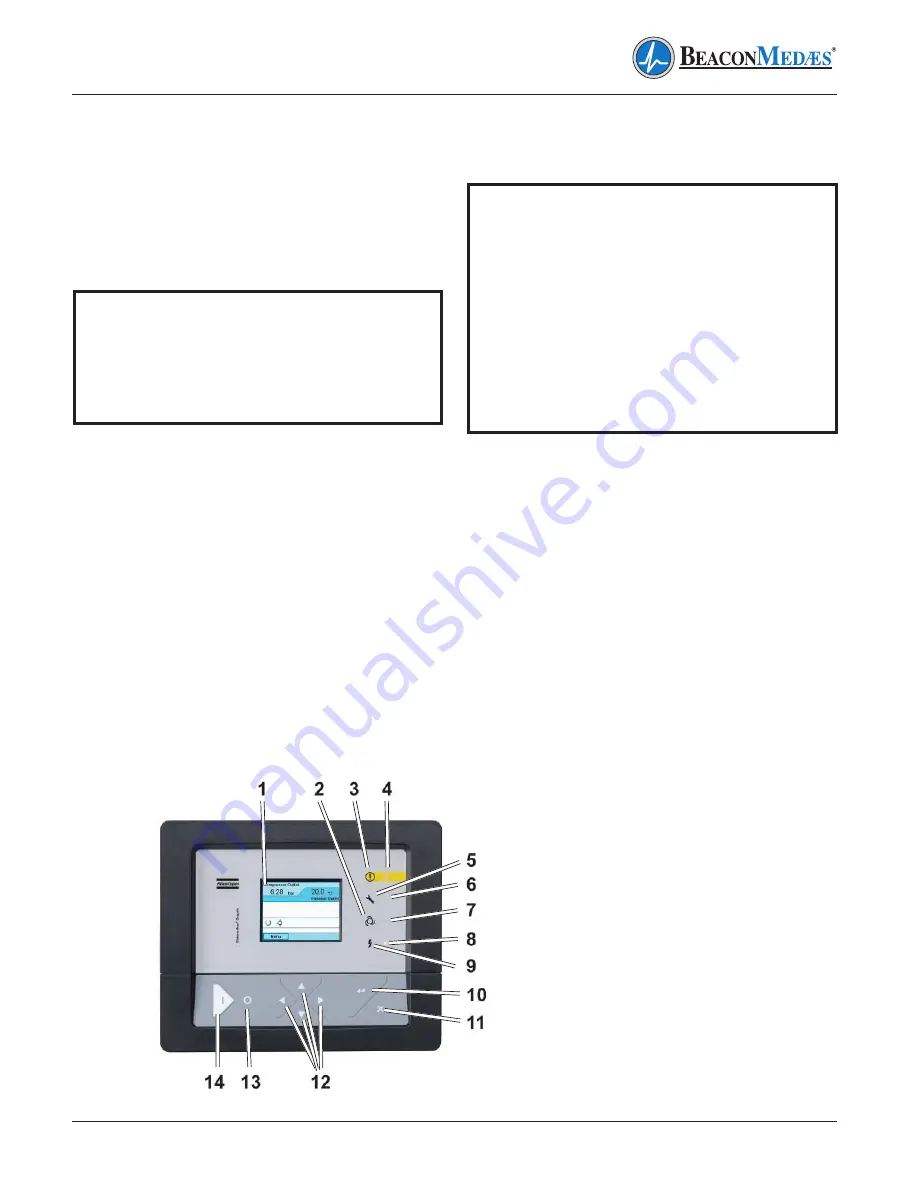
5.  Switch on the voltage and check that the volt-

age on LED (8) lights up (FIG 3.2.2).

6.  Press start button (14). The compressor 

starts running and automatic operation LED 

(7) lights up (FIG 3.2.2).

WARNING!

When the compressor is stopped and 

automatic operation LED (8) is on, the 

compressor may start automatically. If 

the start/stop timer is active, the com-

pressor may start automatically, even if it 

was stopped manually. Consult the user 

manual for Elektronikon Regulator, sec-

tion “Programming Clock Function” in the 

“Operation & Maintenance Manual” sup-

plied with each compressor.

FIG 3.2.2 Compressor Control Panel

Summary of Contents for Z MED Medical Air System

Page 1: ...Installation Operation and Maintenance Instructions Z MED Medical Air System Part number 4107 9022 67 Revision 00 10 April 2018 ...

Page 2: ......

Page 3: ...include the machine serial num ber and be directed to BeaconMedæs 1059 Paragon Way Rock Hill SC 29730 Tech Services 1 888 4MEDGAS 1 888 463 3427 Fax 803 817 5750 BeaconMedæs reserves the right to make changes and improvements to update products sold previously and support materials without notice or obligation Installation Operation and Maintenance Manual Z MED Medical Air Systems W Central Contro...

Page 4: ......

Page 5: ... Network Connection 2 7 1 CAN Connection 2 8 CAN Cable Connectors 2 8 1 Cable 2 8 2 Connector Cabling Procedure 2 8 3 Terminal Connector Cabling 2 8 4 Node Connector Cabling 2 8 5 Line Terminations 2 9 Parts List 3 0 System Operation 3 1 Prestart up 3 2 Initial System Start Up 3 2 1 Compressor Initial Start Up 3 2 2 Compressor Start Up 3 2 3 Dryer Initial Start Up 3 3 System Normal Start Up 3 4 No...

Page 6: ...rk Connection See 2 0 Installation Section 2 7 A 4 Central Control Panel Parts and Functions A 5 Display Description A 5 1 ES 6 Status A 5 2 ES 6 Controls A 5 3 Status of Connection Channels A 5 4 Basic Status A 5 4 1 Exception Status A 5 5 Compressor Status A 5 6 Errors Warnings and Alarm Status A 6 Parameters A 6 1 Parameters A 6 1 1 Parameter Listing A 6 1 2 Configuration Listing A 6 1 3 Settin...

Page 7: ...B 1 1 General Precautions B 2 Compressor Control Panel Parts and Functions Mk4 B 3 Function of Control Programs B 4 Navigating through the On Screen Menu Fixed Speed Compressor B 5 Parameters Fixed Speed Compressor B 5 1 Parameter Listing B 5 2 Configuration Listing B 6 Navigating through the On Screen Menu Variable Speed Compressor VSD B 7 Parameters Variable Speed Compressor VSD B 7 1 Compressor...

Page 8: ... Cycles D 1 2 Continuous Purge Mode D 1 3 Controlled Purge Mode D 2 Basic Dryer Operation CD35 65 D 3 Basic Dryer Operation CD100 300 D 4 Operation D 4 1 Initial Start Up D 4 2 Procedure to Switch Off the Dryer D 4 3 Normal Start Up D 4 4 Maintenance Shut Down D 4 5 DC1 Controller for CD35 65 D 4 5 1 Control Panel D 4 5 2 Main Screen D 4 5 3 Selection Menu D 4 5 4 Alarm Screen D 4 5 5 Editing Para...

Page 9: ... E 8 Dew Point Sensor Calibration E 9 Dew Point Sensor Replacement Appendix F CO Transmitter F 1 General Information F 2 Introduction F 3 Specifications F 4 Power Connection F 5 Alarms F 6 Operation F 7 Maintenance F 7 1 Maintenance Schedule F 8 Sensor Checkout and Replacement F 9 Calibration F 9 1 Zeroing Transmitter F 9 2 Transmitter Calibration F 10 Troubleshooting F 11 Accessories and Replacem...

Page 10: ...nlet must be placed in an area free of toxic or hazardous contaminants It must be kept away from ETO exhaust vents vacuum exhaust vents areas close to automotive exhausts etc in accordance with NFPA 99 Prior to using the Desiccant Dryer System the medical facility must have a Certifier perform all installation tests as specified in NFPA 99 The medical facility is also responsible for ensuring that...

Page 11: ...ressor Drive and Motor The compressor is a two stage oil free compressor block consisting of separate low and high pressure rotary tooth compressor elements flanged to a common step up gearbox The compressor elements are air cooled The high and low compressor elements are supplied with safety relief valves ZT compressors are provided with an air cooled oil cooler intercooler and aftercooler An ele...

Page 12: ...include a combination particulate and coalescing filter with an automatic drain The duplexed final line filters consist of a 1 micron particulate filter and one active carbon filter duplexed final line regulators single oil indicator and duplexed safety relief valves shall be factory mounted and piped All filters shall have element change indicators Central Control System The mounted and wired cen...

Page 13: ...inimize damaging the transmitters Walk along the route the unit must travel and note dimensions of doorways and low ceilings All equipment should be positioned to ensure easy access to all four sides to perform routine maintenance and allow high visibility of indicators and gauges 2 3 Location The Z MED system should be installed indoors in a clean well ventilated environment Areas of excessive du...

Page 14: ...or on a voltage other than the voltage specified on the compressor nameplate All customer wiring should be in compliance with the National Electrical Code and any other applicable state or local codes WARNING Electrical power for the central control system must be supplied from the equipment system branch of the essential electrical distribution Checkthecontrolvoltage phase andampratings before st...

Page 15: ...channel 2 Node ID 2 Connection channel 6 Node ID 6 Central Controller Node ID 30 FIG 2 7 CAN Network Connection Method daisy chained from one devise to the next The CAN network acts as a universal communica tion system which can be used for both con trol and monitoring See FIG 2 7 2 8 CAN Cable Connectors Two types of connectors are used normal node and service node See FIG 2 8 Can Connectors A se...

Page 16: ...2 4 Z MED Medical Air System 4107 9022 67 00 2 0 Installation FIG 2 8a Service CAN Connector FIG 2 8 CAN Connectors FIG 2 8b Normal CAN Connector ...

Page 17: ...but then a repeater has to be used Contact BeaconMedæs Technical Services de 2 8 3 Terminal Connector Cabling For the connector at the beginning and end of the network the cable should be connected to the terminals designated 1C 1C and GND as shown in FIG 2 8 3 Beginning End Connector Wiring Make sure that the wire shielding touch es the shielding plate of the connector Close the connector and set...

Page 18: ...erminal 1C Orange wires to terminal 1C FIG 2 8 3 Beginning End Wiring Connection FIG 2 8 3a Connector Switch Setting Outgoing wire Blue wires to terminal GND White Orange wires to terminal 2C Orange wires to terminal 2C Make sure that the wire shielding touches the shielding plate of the connector Close the connectors and set the terminating switch OFF See FIG 2 8 4a Connector Switch Setting Plug ...

Page 19: ...at the beginning and at the end of the network cable In the connectors as specified in FIG 2 8 5 this termination function is included and can be set by means of a small terminator switch Make sure this switch is in the ON posi tion for both the first and last device and in the OFF position for all other devices Both connec tor types are equipped with this switch FIG 2 8 4 Middle Wiring Connection...

Page 20: ...Air System 4107 9022 67 00 2 0 Installation Description Part No Qty Required Normal Connector 1088001728 Each Service Connector 1088001727 Each Cable 0017261013 Per meter FIG 2 8 5 Connector Switch Setting 2 9 Parts List ...

Page 21: ...ore starting the Z Med Medical Air System check to see that volt age amperage and wire size are appropriate CAUTION Electrical service must be as speci fied or damage to equipment may occur Open the electrical cabinet by loosening the fas teners on the front CAUTION Vibration during shipment and in stallation can loosen electrical terminals fuse inserts and mechanical connections Tighten as necess...

Page 22: ...ck that the gear casing is filled with oil the level should be in the middle of the sight glass Add oil via the filler plug if necessary FIG 3 2 1b 4 Check that the electrical connections cor respond to the local codes The installation must be grounded and protected by fuses in all phases An isolating switch must be pro vided 5 Check the connections at the primary sides of transformers T1 and T2 S...

Page 23: ...lve 2 to in crease the temperature difference and de crease the aftercooler cooling The aftercooler outlet temperature must be set at 6 8 C 10 8 14 4 F above the cooling water inlet temperature 12 On All compressors Run the compressor for a few minutes and check that it operates normally tation while the motor is coasting to a stop The arrow on the gear casing indicates the correct rotation direct...

Page 24: ...Manual supplied with each compressor 1 Check the oil level which must be in the mid dle of the sight glass SG FIG 3 2 1b top off if necessary with the correct type oil 2 On ZR check the setting of the valves 1 2 3 FIG 3 2 1c as described in section 3 2 1 This can be overlooked if after previous op eration the settings of these valves have not been disturbed 3 Close the manual condensate drain 4 Op...

Page 25: ...oring the dew point and CO levels in the discharge air The CCS distributes the run time between mul tiple compressors connected in the CAN net work see Section 2 0 Installation To connect the Elektronikon III controlled compressors to the CCS a dongle is required see Appendix A FIG A 2 The status of each compressor can be checked on the CCS control screen Operating parameters of the system are acc...

Page 26: ...or proceed as follows 1 Close the air outlet valve and stop the com pressor Press the test button on top of the electronic water drains to depressurize and open the drain valve FIG 3 2 1c 2 Switch off the voltage and disconnect the compressor from the mains 3 Shut of and depressurize the part of the air net which is connected to the outlet valve 4 Disconnect the compressor air outlet pipe from the...

Page 27: ...on Check oil level Check oil level switch operation Check tighten all wire connections Power failure Main fuse blown Fuse blown in control circuit Replace fuse Replace fuse Compressor shuts off unexpectedly Overload tripped on starter Faulty pressure transducer High temperature switch activated Low oil pressure Reset check for system overload Adjust or replace Allow unit to cool reset switch check...

Page 28: ...e is not discharged from con densate traps during operation Discharge flex line clogged Electronic water drain malfunc tioning Check and correct as necessary Contact BeaconMedæs Motor overheating Low voltage Defective motor Check for proper supply voltage Contact BeaconMedæs Compressor runs hot Wrong rotation Incorrect pressure setting Faulty compressor valves Intake filter clogged Switch motor le...

Page 29: ...cer System piping leaks Adjust or replace Repair leaks High air temperature Bad room ventilation Air Filter Clogged Insufficient cooling water ZR Formation of scale dirt Improve room ventilation Replace filter Check water temperature increase water flow Contact BeaconMedæs Dryer not Cycling Main power disconnected Dryer power switch off Power failure Main fuse blown Fuse blown in control circuit S...

Page 30: ...urize the dryer Inspect the desiccant and replace if fouled Inspect prefilters if fouling is noted Soap bubble test the dryer outlet and downstream piping Repair all leaks noted Backpressure on a desiccant chamber during regeneration cycle Dirty or fouled muffler Switch off power remove purge muf fler and clean or replace Maximum Capacity System undersized Incorrect pressure setting Faulty pressur...

Page 31: ...k flow through dew point sensor Weekly Check for flow blockage Check operation of safety valve Weekly Manually release pressure Check nuts bolts fittings etc Monthly Inspect and tighten Clean compressor Every 3 months Clean if necessary Check for possible leaks Every 3 months Repair or replace components Check compressor coolers Every 3 months Clean if necessary Calibrate CO sensor Every 6 months ...

Page 32: ...oil has a long service life and ensures optimum lubrication Never mix oils of different brands or types See chart for part numbers and available sizes 5 2 Spare Parts For Desiccant Dryer spare parts see Appendix D 6 1 thru D 6 5 For Compressor spare parts and servicing procedures refer to ZT ZR Instruction Book supplied with each compressor unit Quantity Part Number 1 Gallon Can 2908 8503 00 20 Li...

Page 33: ...22 67 00 Model Number Serial Number Installation Date 6 0 Maintenance Record Date of Service Hours Ambient Temp Air Leaks Condensate Drains Inlet Filter Dryer Filters Manual Valve Oper Dewpoint Flow Oil Level Alarms Misc Serviced By Notes ...

Page 34: ...22 67 00 Model Number Serial Number Installation Date 6 0 Maintenance Record Date of Service Hours Ambient Temp Air Leaks Condensate Drains Inlet Filter Dryer Filters Manual Valve Oper Dewpoint Flow Oil Level Alarms Misc Serviced By Notes ...

Page 35: ...evels in the discharge air The Central Control System distributes the running time between multiple compressors connected in the CAN network see A 3 CAN Network Connection To connect Elektronikon III controlled compressors a dongle is required see FIG A 2 The status of each compressor can be checked on the control screen Operating parameters are accessible via the menu A 2 1 Single Point Pressure ...

Page 36: ...ready to be started will be taken into account A compressor can be unavailable due to Minimum stop time Shut down condition Emergency stop pressed No communication A 2 6 Automatic Restart After Voltage Failure The controller has a function for automatic restart after voltage failure For controllers leaving the factory this function is made active After power restoring the controller restarts regul...

Page 37: ... service warning or shut down warning condition exists Flashes if a shut down condition exists if an important sensor is out of order or after an emergency stop 8 Automatic Operation LED Indicates that the regulator is automatically controlling the compressor 9 Function Keys Keys to control and program the compressor The functions of the keys vary depending on the displayed menu The actual functio...

Page 38: ...P A stop condition is active which stops all compressors The stop symbol does not only occur after an manual stop but can be shown after one of the follow ing actions Manual stop button pressed Stop action through weekly timer Stop command over CAN Stop action via a switch LOCAL OPERATION Is shown when the ES 6 is set to local This action disables the control of the ES 6 and gives the pressure con...

Page 39: ...p operation The start stop buttons on the Elektronikon module of the ES 6 are not active ES 6 LAN START STOP The ES 6 is started and stopped over a LAN network The commands can be giv en over a fieldbus interface Modbus Profibus connected to the LAN network In the middle the following symbols can appear ES PRIORITY SCHEME 1 Shows that priority scheme 1 is active The priority scheme gives a priorit...

Page 40: ...es of the active compressors are indicated Two different types of compressors can be visualized Fixed speed compressor Variable speed compressor A 5 4 Basic Status The basic status for each compressor is unique Stopped Unloaded Loaded FIG A 5 4 Basic Status Symbol Description Fixed speed compressor Status compressor stopped Status compressor unloaded Status compressor loaded Symbol Description Var...

Page 41: ...ssor Status Symbol Designation Description Electro pneumatic Compressor X No valid compressor type X is blinking when An unknown compressor type is detected A second variable speed drive VSD compressor is detected No communication is blinking when For fixed speed or variable speed compres sors No reply from the connected compressor within a timeout For electro pneumatic compressor status read from...

Page 42: ...tions are located under Modify Parameters on the compressor controller Symbol Description SENSOR ERROR The main pressure sensor 4 20mA indicates an error I O ERROR An I O buss error occurred This can be one of the following errors Dongle required Dongle no longer present WARNING SERVICE REQUIRED If a service warning protection is set to an input of the ES 6 controller by default no service protect...

Page 43: ...e of connection channel 2 20 seconds 30 seconds Start Load Reac ID3 Start Load Reaction time of connection channel 3 20 seconds 30 seconds Start Load Reac ID4 Start Load Reaction time of connection channel 4 20 seconds 30 seconds Start Load Reac ID5 Start Load Reaction time of connection channel 5 20 seconds 30 secondsi Start Load Reac ID6 Start Load Reaction time of connection channel 6 20 second...

Page 44: ...iority Scheme 2 Priority level for connection channel 2 1 1 S2 ID3 Priority Scheme 2 Priority level for connection channel 3 1 1 S2 ID4 Priority Scheme 2 Priority level for connection channel 4 1 1 S2 ID5 Priority Scheme 2 Priority level for connection channel 5 1 1 S2 ID6 Priority Scheme 2 Priority level for connection channel 6 1 1 Running Hours ID1 Scheme 2 Priority level for connection channel...

Page 45: ...eters to be protected by a user defined password Not Activated Activated Node ID ES 6 Node Identification number on the CAN network 31 30 Comp 1 Connection This parameter determines how the compressors are connected to the ES 6 regulator Physical connection LAN or Digital Link Hardwired Physical connection for connection channel 1 LAN LAN Comp 2 Connection Physical connection LAN or Digital Link H...

Page 46: ... using the scroll buttons to select the number and tabular button to move between the numbers 6 Select function button F1 under Prog on display screen 7 Re enter 4735 to confirm password 8 Select function button F1 under Prog on display screen to activate password A 6 2 Central Control Panel A 6 2 1 Navigating through the On Screen Menu Ref FIG A 5 Central Control Panel To view the existing ES 6 c...

Page 47: ... 2 4 Measured Data Menu Flow Diagram F1 on the main display The following menu flow diagrams will show how to navigate through each main category A 6 2 3 Status Data The Status Data menu displays the status of all the shutdown and Measured data warn ings See FIG A 6 2 3 Status Data Menu Flow Diagram A 6 2 4 Measured Data The Measured Data menu displays all the cur rent conditions of the system and...

Page 48: ...at the main screen The display Loc just above the F3 button will turn off and the FIG A 6 2 4 Measured Data Menu Flow Diagram Continued center display will change from automatic operation to local operation See FIG A 5 1 ES 6 Status for respective operation symbols Once in local mode navigate to the Test menu to test outputs See FIG A 6 2 6 Test menu flow diagram To return the system to automatic ...

Page 49: ...A 15 Z MED Medical Air System 4107 9022 67 00 FIG A 6 2 5 Counters Menu Flow Diagram FIG A 6 2 6 Tests Menu Flow Diagram Appendix A Central Control System ...

Page 50: ...A 16 Z MED Medical Air System 4107 9022 67 00 FIG A 6 2 7 Parameters Menu Flow Diagram Appendix A Central Control System ...

Page 51: ...A 17 Z MED Medical Air System 4107 9022 67 00 FIG A 6 2 7 Parameters Menu Flow Diagram Continued Appendix A Central Control System ...

Page 52: ...A 18 Z MED Medical Air System 4107 9022 67 00 FIG A 6 2 7 Parameters Menu Flow Diagram Continued Appendix A Central Control System ...

Page 53: ...ers Clock Functions The Clock Functions section is password pro tected and can only be changed by a certified BeaconMedæs service technician Contact Bea conMedæs Technical Services department at 1 888 4MEDGAS 888 463 3427 for assistance A 6 2 10 Modify Parameters Configuration The Configuration section is password pro tected and can only be changed by a certified BeaconMedæs service technician Con...

Page 54: ...A 20 Z MED Medical Air System 4107 9022 67 00 FIG A 6 2 8 Protections Menu Flow Diagram Appendix A Central Control System ...

Page 55: ...A 21 Z MED Medical Air System 4107 9022 67 00 FIG A 6 2 8 Protections Menu Flow Diagram Continued Appendix A Central Control System ...

Page 56: ...A 22 Z MED Medical Air System 4107 9022 67 00 FIG A 6 2 9 Clock Function Menu Flow Diagram FIG A 6 2 10 Configuration Menu Flow Diagram Appendix A Central Control System ...

Page 57: ...A 23 Z MED Medical Air System 4107 9022 67 00 FIG A 6 2 10 Configuration Menu Flow Diagram Continued Appendix A Central Control System ...

Page 58: ...A 24 Z MED Medical Air System 4107 9022 67 00 FIG A 6 2 10 Configuration Menu Flow Diagram Continued Appendix A Central Control System ...

Page 59: ...essor A 7 1 2 Protecting the Compressor Several temperature and pressure sensors are provided on the compressor If one of these measurements exceeds the programmed shut down level the compressor will be stopped This will be indicated on the control display A 7 1 3 Shut Down Warning If the CCS detects a temperature or pressure just below the programmed shut down level this will be indicated on the ...

Page 60: ...the compressor installation Stick labels on the control panels of the compressors connected to the ES 6 as well as on an obvious place inside these compressors warning the operator that the compressor is remotely started and stopped by a separate controller These labels must warn the operator that after voltage failure the controller can remotely start and stop the compressors depending on the air...

Page 61: ...wnwards through the display 4 Tabular Key Key to select the parameter indicated by the horizontal arrow Only the parameters followed by an arrow pointing to the right can be modified 5 Function Key Keys to control and program the compressor The functions of the keys vary depending on the displayed menu The actual function is indicated just above the relevant key 6 Voltage on LED Indicates that the...

Page 62: ...ver load and service condition Measured Data Calling up the actually measured data and the status of a number of inputs Counters Calling up the number of running hours loaded hours motor starts Test Allows a display test Modify Parameters Modifying the parameters for parameters e g loading pressure protections e g air temperature shut down level service plans clock functions automatic compressor s...

Page 63: ...B 3 Z MED Medical Air System 4107 9022 67 00 Appendix B Compressor Controller Mk4 B 4 Navigating through the On Screen Menu Fixed Speed Compressor Ref FIG B 1 Compressor Control Panel ...

Page 64: ...f Pressure band 1 8 bar 105 psi Start Load Reac IDT Start Load Reaction time of connection channel 1 Time which the compressor has to run in load condition after a start com mand 20 seconds 20 seconds Y Time 10 seconds 10 seconds Load Reaction Time which the compressor has to run in load condition after start command 10 seconds 10 seconds Stop Reaction Time which the compressor has to stop after a...

Page 65: ...band 1 or 2 Press Band 1 Press Band 1 Auto Restart Allows the ES 6 to restart after a power failure Not Activated Infinite Password This feature allows the parameters to be pro tected by a user defined password Not Activated Activated Language English English Time E S T E S T Date Current Current Date Format DD MM YY MM DD YY Pressure Units Bar psi Temperature Unit C C Vibration Units microns micr...

Page 66: ... VSD Ref FIG B 1 Compressor Control Panel B 7 Parameters Variable Speed Compressor VSD The compressor parameters are separated into the three following sections B 7 1 Compressor motor B 7 2 Parameters and B 7 3 Configura tion All three sections are located under Mod ify Parameters on the compressor controller See B 6 for on screen navigation diagram ...

Page 67: ... seconds 5 seconds Power recovery time Maximum allowed power down time to accept the Automatic Restart After Voltage Failure ARAVF 3600 seconds oo sec Restart Delay Start delay after voltage is restored 5 seconds 5 seconds Communication Time out 30 seconds 30 seconds Setpoint 1 95 psi 95 psi Setpoint 2 95 psi 95 psi Indirect stop level 1 4 psi 4 psi Direct stop level 1 15 psi 15 psi Indirect stop ...

Page 68: ...YY Pressure Units Bar psi Temperature Units C F Vibration Units microns microns Level Units mm inch Flow Units LPS CFM Volume Units Liter Gallon Automatic restart Allows the ES 6 to restart after power failure Not activated Infinite Password This feature allows the parameters to be protected by a user defined password See B 8 to set password Not activated Activated M C C Not activated Not activate...

Page 69: ...the menu 2 Pictograph Automatic operation 3 Pictograph General alarm 4 General Alarm LED Flashes if a shutdown warning condition exists 5 Pictograph Service 6 Service LED Lights up if service is needed 7 Automatic Operation LED Indicates that the regulator is automatically controlling the compressor 8 Voltage On LED Indicates that the voltage is switched on 9 Pictograph Voltage on 10 Enter Key Key...

Page 70: ... is running the icon is rotating Compressor Status Motor stopped Running unloaded Running loaded Machine control mode Local start stop Remote start stop Network control Automatic restart after voltage failure Automatic restart after voltage failure is active Week timer Week timer is active Active protection functions Emergency stop Shutdown Warning Service Service required C 3 1 Status Icons ...

Page 71: ...er Mk5 C 3 2 Input Icons C 3 3 System Icons Icon Description Pressure Temperature Digital input Special protection Icon Description Icon Description Compressor element LP HP Filter Dryer Motor Fan Failure expansion module Frequency Converter Network problem Drain General alarm ...

Page 72: ... Appendix C Compressor Controller Mk5 C 3 5 Navigation Arrows Icon Description Icon Description Input Service Outputs Event history saved data Alarms Warnings shutdowns Access key User password Counters Network Test Setpoint Settings Info Icon Description Up Down ...

Page 73: ...cy stop and to have access to all data collected by the regulator Inputs Menu Call up information regarding the actually measured data and the status of some inputs such as the emergency stop switch Outputs Menu Call up information regarding the actual status of some outputs such as the condition of the Fan overload contact the Emergency stop contact etc Menu Icon Counters Call up the running hour...

Page 74: ...ime Time which the compressor has to stop before restarting 20 seconds 20 seconds Unload Time 30 seconds 30 seconds Start check time 20 seconds 20 seconds Automatic Restart Not activated Infinite Maximum Power Down 15 seconds 15 seconds Restart 0 seconds 0 seconds Ethernet On On CAN CAN must be off to change CAN address and communication profile Off On CAN Address 31 Node ID Communication Profile ...

Page 75: ... compressor controller Name Description Controller Default Value Beacon Medaes Value Language in use Language used English English Time Clock function Local Local Date Date Date Date Format DD MM YY MM DD YY Password This feature allows the parameters to be protected by a user defined password Not activated Activated Pressure Units Bar Bar Temperature Units F F Vibration Unit Mils Mils Level Unit ...

Page 76: ...ection Requires password to activate 4735 Off Off Minimum Stop Time 5 seconds 5 seconds Minimum Speed Varies Default Minimum Speed Factor 0 0 Proportional Band 10 10 Integration Time 6 seconds 6 seconds 1 Typical settings shown for lead compressor Lower these settings by 5 psi for each remaining compressor so that all compressors have a different local set point Name Description Controller Default...

Page 77: ...ller Default Value Beacon Medaes Value Language in use Language used English English Time Clock function Local Local Date Date Date Date Format DD MM YY MM DD YY Pressure Units Bar PSI Temperature Units C F Vibration Unit MM MM Flow Units LPS CFM Volume Unit Liter Gallon Display Timeout 5 min 5 min Automatic Restart Allows the machine to restart after power failure Not activated Infinite Password ...

Page 78: ... in a drying cycle throughout normal dryer operation The opposite off line tower is in a regeneration cycle for removal of the previously adsorbed moisture content See D 2 and D 3 for Basic Dryer operation D 1 2 Continuous Purge Mode When the dryer selector switch on the Central Control System CCS panel is in the continuous purge position the dryer will shift towers based on a factory pre set time...

Page 79: ...ssure dewpoint sensor which is optionally available While the desiccant in one tower dries the compressed air the desiccant in the second tower is being regenerated Regeneration of the desiccant is achieved by means of purge air from the drying tower The compressed air entering the dryer is led to one of the towers by means of one of the two 3 2 valves The position of the 3 2 valves is controlled ...

Page 80: ... the controller jumps automatically to status 5 or 12 equalization phase After that the Stop status 0 will be reached The following start command will restart the sequence from the state 2 or 9 The same happens when the power is switched off On dryers equipped with the DC1 controller when dryer is in purge saving mode the controller jumps automatically to status 5 or 12 equalization phase When the...

Page 81: ...ses through a small orifice D into TOWER 2 and is expands to atmospheric pressure This extremely dry low pressure air flows downward through the tower regenerating the desiccant The regenerating air is then exhausted through a purge valve E2 and exhaust muffler F2 to atmosphere After a set time the SMART relay closes the purge exhaust valve E2 allowing TOWER 2 to repressurize slowly At the end of ...

Page 82: ...on trolled purge position Verify proper opera tion as described in D 2 or D 3 15 On the completion of the conditioning run slowly open the source isolation valve The dryer will now be fully operational Appendix D Desiccant Dryer D 4 2 Procedure to Switch Off the Dryer 1 Put second dryer on line by repeating steps 4 thru 7 above 2 CLOSE the dryer outlet isolation valve 3 SWITCH OFF the electrical s...

Page 83: ...er Increments the data value No action ENTER Displays the selection menu Cancels the displayed alarm for one minute alarm acknowledgment Selects the pointed menu and activates it Returns to the selection menu Cancels the service alarm if pressed for 5 seconds Starts the parameter editing Selects the numerical data digits Confirms the modi fied value Pressed for at least 2 sec onds returns to the s...

Page 84: ...TING SHIFTING Adsorbing ADSORBING ADSORBING Pressure relief DEPRESS DEPRESS Regeneration REGENERAT REGENERAT Pressure equalize EQUALIZE EQUALIZE Freeze FREEZE FREEZE Standby STANDBY STANDBY Blowing off BLOW OFF BLOW OFF In the upper left area of the screen an animated icon is present In the upper right area the current working phase countdown and the measured dew point are visualized When the PDP ...

Page 85: ...rn to the Main screen or wait approximately 30 seconds D 4 5 4 Alarm Screen When an alarm arises the display shows the fol lowing image When one or more alarms are active the alarm screen overrides the main screen In the upper right area the current alarm num ber and the total active alarms number are visu alized In the lower area the current alarm description is displayed If more than one alarm i...

Page 86: ...l error Reset all settings to the default value Switch off the controller and switch it on again Call your sup plier if the fault persists Lit con tinuously Possible alarm causes In the upper right area the current parameter number and the total modifiable parameters number are visualized In the lower area the current parameter de scription and value are displayed Editor button functions Button Fu...

Page 87: ...s 1 999 minutes All other parameters are protected by a password Step Button Involved Action 1 RIGHT or LEFT To select the parameter to be modified 2 ENTER Starts the modification procedure If the parameters is a selection value e g a language or a boolean value On or Off go to step 3 If the parameters is a numerical value press the ENTER button repeatedly as required 3 RIGHT or LEFT Modifies the ...

Page 88: ...s The dryer s electrical power supply must be deenergized before any electrical maintenance or repair work is conducted CAUTION Each component has been selected to compliment the performance of the other components of the system Therefore use of unauthorized parts or improper operation will degrade system performance IMPORTANT Water molecules can diffuse through a pinhole size leak even though pre...

Page 89: ...olate and depressurize the pre filter assembly Inspect pre filter cartridges and end seals for loosening and or damage Tighten or replace as necessary Inspect the pre filter automatic drain valve Ensure that it is not clogged and is draining properly Repair or replace as necessary if a problem is noted Replace muffler Shutdown and depressurize the dryer Inspect the desiccant and replace if fouled ...

Page 90: ...ndix D Desiccant Dryer D 6 Maintenance A compressed air dryer should give long and trouble free operation if the recommended pre ventative maintenance program is carried out The following is a recommended schedule 1 Quarterly procedure Clean the auto drain in the coalescing filter Monitor the backpres sure on the purging tower If the gauge reads more than 0 psig when purging check the purge muffle...

Page 91: ...45 2901 0563 00 2 50 2901 0611 00 2 2901 0611 00 2 CD65 60 2901 0563 00 2 70 2901 0611 00 2 2901 0611 00 2 CD110 140 2901 0563 00 2 130 2901 0611 00 2 2901 0611 00 2 CD150 180 2901 0563 00 2 170 2901 0611 00 2 2901 0611 00 2 CD185 220 2901 0563 00 2 210 2901 0611 00 2 2901 0611 00 2 CD250 310 2901 0563 00 2 310 2901 0611 00 2 2901 0611 00 2 CD300 310 2901 0563 00 2 310 2901 0611 00 2 2901 0611 00 ...

Page 92: ...5 1617 6164 04 2 CD250 2 CD300 2 Dryer Size Part No Qty CD35 1310 2565 01 2 CD65 1310 2565 01 2 CD110 1310 2565 01 2 CD150 1310 2565 01 2 CD185 1310 2565 01 2 CD250 1310 2565 01 2 CD300 1310 2565 01 2 Type Desiccant Heatless Design Pressure 160 psig Operating Pressure 100 psig Max Ambient Temperature 105 F 40 C Pressure Dew Point Capability 100 psig 40 F 40 C Desiccant Activated Alumina Power 115V...

Page 93: ...tainless Steel 316 3 Sensor protection Ceramic E 4 Operation Although the correct operation of the transmit ter is not sample flow dependent it is important that flow velocity through the sample source to the sample block is high enough to avoid long lead time lags in response to changes in mois ture at the sample source A flowmeter has been installed and set at 1 0 2 0 SCFH to ensure proper flow ...

Page 94: ... flowmeter Weekly Check for proper flow 1 0 2 0 SCFH Check Transmitter accuracy Every 12 months Verify dewpoint sensor accuracy contact BeaconMedæs Recalibration Every 2 years See Section E 8 Replace sensor Every 5 years See Section E 9 WARNING Electrical shock hazard No repair should ever be attempted by anyone not having experience in the repair of devices of this nature Failure to follow proper...

Page 95: ...through dew point sensor Check flow No power No incoming power Verify line power is being supplied Erratic Display Unit defect Contact BeaconMedæs High Dew Point Air is not being dried Faulty sensor Verify that the dryer is not being bypassed Check flow Replace sensor E 8 Dewpoint Sensor Calibration The dewpoint sensor is shipped to you pre cali brated no user calibration is required Contact Beaco...

Page 96: ...eared by the operator F 6 Operation CAUTION At initial startup if the unit is reading a gas level do not make any adjustments for a few hours until the unit has a chance to settle in and stabilize If gas readings remain high or below zero 0 re calibration may be needed We also recommend checking the compressor s air intake first Appendix F CO Transmitter WARNING Before starting any installation ma...

Page 97: ...rience in the repair of devices of this nature Failure to follow proper repair procedures can result in serious injury F 9 Calibration F 9 1 Zeroing Transmitter The following procedure should be used for ze roing the transmitter See F 11 Accessories and Replacement Parts for zero gas part numbers 1 Turn on the power and allow the transmit ter to warm up for several hours to stabi lize 2 Disconnect...

Page 98: ...C Turning the adjusting screw counterclockwise will reduce the voltage output Turning it clockwise will raise the voltage output 6 Repeat the zeroing procedure and calibration procedure once more to ensure the transmitter is set properly 7 Reinstall the cover on the transmitter 8 Reconnect the inlet air line from the dryer FIG F 9 1 CO Transmitter Assembly ...

Page 99: ...essure Before servicing the CO sensor do the follow ing 1 Unplug sensor s or turn off monitor 2 Depressurize the CO sensor Note Remote alarms will be activated Problem Possible Causes Solution CO Alarm 10 ppm or above Inlet air to the medical air system is contaminated Move air inlet location or remove source of CO contamination Monitor will not calibrate Sensor depleted Replace sensor CO Alarm CO...

Page 100: ...me for which the manufacturer cannot be responsible To request a quotation of or place an order for recommended or emergency spare parts please contact BeaconMedæs Technical Services de partment at 1 888 4MEDGAS 888 463 3427 G 2 Function The Oil Indicator is a calibrated measuring instrument used to detect aerosol mist levels of oil entrainment that may be present in the medical air system Sensiti...

Page 101: ...e dark red col umn not light pink area if present If dark red column is not visible discontinue test there is no measurable amount of oil pres ent in the air stream 4 If dark red column is visible record the actual time and unit mark on the indicator and close the needle valve Part Number Qty Required GAG08 002 1 WARNING Do not disturb the factory adjusted torque on the retaining nut that holds th...

Page 102: ...G 3 Z MED Medical Air System 4107 9022 67 00 Appendix G Oil Indicator FIG G 2 Conversion Chart for Oil Indication ...

Page 103: ......

Page 104: ...1059 Paragon Way Rock Hill SC 29730 888 4 MEDGAS 888 463 3427 Fax 803 817 5750 www beaconmedaes com ...

Reviews: