background image

HBZMXSIB/10/16SD-PR-1

Page 76

Appendix B

Flicker Adjustment

The mono multiplexer units do not require flicker adjustment.

For colour multiplexer units, do the following.

Before recording any cameras, the two decoder channels need to be calibrated to
reduce flicker on playback.

Note

You must use camera 1 for this set-up.

1) Display camera 1 full screen on Monitor-A.

Camera-1 must be in full resolution mode (frame display) and not it half resolution
mode (field display). The half resolution mode is indicated on the monitor by the
presence of the - character to the left of the time and date display. Press the
camera 1 key to toggle this feature on and off.

2) Normally the picture will flicker. Reduce the flicker by pressing the up or down
arrow keys 

.

Note

These are not repeating keys.  Do not hold them down. They must be released
each time you press them.

These settings are stored in the battery backed up memory, however, every time a
unit is reset using the RUN/CLR jumper, or by commanding a Factory Settings
reset, this procedure must be repeated.

Summary of Contents for ZMX/BD/10

Page 1: ...HBZMXSIB 10 16SD OP 1 Page 1 Operating Instructions ZMX BD 10 ZMX BS 10 ZMX CS 10 Multiplexers...

Page 2: ...HBZMXSIB 10 16SD PR 1 Page 1 Programming Instructions ZMX BD 10 ZMX BS 10 ZMX CS 10 Multiplexers...

Page 3: ...HBZMXSIB 10 16SD PR 1 Page 2 This page is intentionally blank...

Page 4: ...tore it in a safe place The initial password supplied with the unit for the menu system is Password 1 The password for resetting your multiplexer to the factory settings is Password 2 You should chang...

Page 5: ...HBZMXSIB 10 16SD PR 1 Page 4 This page is intentionally left blank...

Page 6: ...ety information including the Low Voltage Directive and EMC declaration WARNINGS and CAUTIONS which must be observed when installing the unit Section 2 Installation Instructions contains instructions...

Page 7: ...HBZMXSIB 10 16SD PR 1 Page 6 This page is intentionally left blank...

Page 8: ...Description 15 2 5 Connections 16 Camera Inputs 16 VCR 17 Monitor 18 Alarm Inputs And Outputs 18 Vext Input 20 Power 20 3 PROGRAMMING FACILITIES 21 3 1 Initial Actions After Switching On 21 Power Up...

Page 9: ...on Keys 66 Display Options 67 Record and Playback 67 Alarms Events 67 Alarm Responses 67 All Video Inputs and Outputs 67 Camera Switch Input Vext 68 Power 68 Physical Specifications 68 5 FUNCTION LIST...

Page 10: ...the unit and to protect it from overheating these openings must not be blocked or covered This unit should not be placed in a built in installation unless proper ventilation is provided Do not place...

Page 11: ...titutions may result in fire electric shock or other hazards Safety Check Upon completion of any service or repairs to this unit ask the service technician to perform safety checks to determine that t...

Page 12: ...es according to the manufacturers instructions WARNING Do NOT use the 12V power leads in the RS 485 cable UNLESS it is to be used on a one to one connection between a unit with 12V power and a unit wi...

Page 13: ...and temperature limits given in the specification WARNING To reduce the risk of electrical shock do not open covers There are no user serviceable parts inside Refer servicing to qualified service per...

Page 14: ...e with British Standards Institution DISC PD2000 1 A Definition of Year 2000 Conformity Requirements and complies with the four rules set out in the document Rule 1 No value for the current date will...

Page 15: ...ignals S VHS connectors and leads if you are using an S VHS VCR A mains power outlet for your multiplexer which allows for secure isolation your Multiplexer has no ON OFF switch for security reasons i...

Page 16: ...nus With all of the models the front panel contains all the operator control keys and indicators while the video inputs video outputs alarm inputs and outputs and the remote control connectors are hou...

Page 17: ...se train from your VCR see your VCR s instructions This allows the multiplexer to follow automatically the time lapse speeds of the VCR Figure 2 Multiplexer Back Panel Connections Camera Inputs 4 3 2...

Page 18: ...exer For connection to the Vext input the Switch Input option must be used in the VCR Setup in the menu system Note Some time lapse VCRs do not transmit a Vext signal in 3 hour mode In this case if yo...

Page 19: ...k panel Figure 5 The 25 way D type Connector Numbering Figure 5 shows the connector looking towards the rear panel The numbers are labelled on the connector itself although they may be difficult to re...

Page 20: ...espond to macro functions alarms and video loss The relays are active see Figure 7 for the duration of the driving event Connect your application to the alarm output relays resistive loads only Figure...

Page 21: ...or alarms and normal operation to be the same in the RECORD menu The Vext input accepts TTL field synchronised negative going pulse duration 2 5 ms HIGH level 4 5V to 5 5V LOW level 0V The multiplexer...

Page 22: ...he unit Power up all the cameras and the monitor and only then power up the unit by plugging in the 12V DC class 2 isolated supply With the unit in record mode select each camera full screen and check...

Page 23: ...MAIN menu bar will appear once the correct password has been entered Navigating The Menu System You have three menu levels designed in such a way as to make it very easy to navigate around the menu c...

Page 24: ...t sub menu The MENU key is the same as CANCEL The Available Menus The Menu Bar enables you to select Main or Quick Setup To do this highlight the one that you want using the left or right arrow keys a...

Page 25: ...de and the full screen dwell time You get the following pull down menu Note You cannot edit the sequence list for cameo sequencing Record This option is used to specify the order in which images are t...

Page 26: ...ages from the alarmed cameras are to be recorded interleaved exclusive or no change and whether some or all of the alarms are to be enabled or disabled You can view the alarm history for the last 100...

Page 27: ...he monitor and for each camera the motion detection sensitivity record rate and output relay to be used You get the following pull down menu Camera AGC This option is used to specify the signal gain t...

Page 28: ...get the following pull down menu Playback Format This option is used to specify the playback format for a multiplexed tape You get the following pull down menu Camera Enable Camera 01 ENABLE Camera 0...

Page 29: ...ox You must enter the correct password to reset to the factory settings Change Password This option is used to change the password for the menu system You get the following password box When you have...

Page 30: ...or several months If a unit is to be powered down for an extended time 3 months or longer then the battery should be removed during power down and replaced when the unit is ready to be put back into s...

Page 31: ...ing RECORD mode is selected by pressing the RECORD key Record Mode on Simplex and Duplex Multiplexers On a simplex multiplexer RECORD mode is one of the three possible modes RECORD mode must be activa...

Page 32: ...orresponding camera On playback you can select one of several screen formats for display and also choose which cameras to display in which position in a multi screen display VCR Record List You can pr...

Page 33: ...must ensure that the VCR is correctly programmed and has correct alarm inputs Unless the Vext input see below is used it is important that the multiplexer is programmed with the same record speeds as...

Page 34: ...ecord Speed indicator while this switch input is active and detected by the multiplexer Note On power up the autodetection circuit will wait about 15 seconds to check if the VCR starts to output a swi...

Page 35: ...ause the display to sequence between alarmed cameras with a fixed dwell time of 1 second Note During RECORD mode the alarm image on a simplex unit cannot be frozen on Monitor A Recording With Live Mod...

Page 36: ...E mode Monitor A displays multi screen images of several cameras in formats that you can select Regardless of the mode selected Monitor B only displays live analogue full screen images of one camera a...

Page 37: ...d is as follows Multi screen Notes 16 WAY 4X4 16 way multiplexers only 13 WAY 1X12 16 way multiplexers only 10 WAY 2X8 9 WAY 3X3 7 WAY 3X4 QUAD 2X2 PIP 1 in 1 16 WAY repeats from top of list Sequencin...

Page 38: ...lti Screen Displays Any camera can be displayed in any position in the multiplexer multi screen displays The default multi screen displays show the cameras in ascending order In LIVE mode you can disp...

Page 39: ...de Notes If the ZOOM key is pressed with no active cameo selected then the display will switch full screen to the camera displayed in the top left cameo Live Mode Full Screen Displays On Monitor A Res...

Page 40: ...t contains all cameras This default list will display each camera for the default dwell time of 3 seconds in each cycle Full Screen Sequencing On Monitor A Select any full screen display by pressing t...

Page 41: ...on the lower right hand side of the display or else on the top left hand side of the display Changing The PIP Size And Position In LIVE Mode The PIP size and position can be changed during LIVE mode...

Page 42: ...ctive in both LIVE and PLAY modes Editing The Time and Date and Changing The Colours To edit the time and date use the Quick Setup menu or the Time Date sub menu from the Main menu Summer Winter Time...

Page 43: ...then enter a 4 during date set up This is used to start Timed Macros on the correct day The time can be in one of two formats and the date can be in one of three formats The time format can be either...

Page 44: ...screen text on Monitor A will show the status time and date at the time of recording Monitor B will always display live analogue signals No playback images are shown on Monitor B During playback the t...

Page 45: ...d It warns that there may have been events that were not captured during the recording or the tape data may be corrupted Decoding Tape Formats From Different Multiplexers Your multiplexer can decode t...

Page 46: ...k the system will display a blank screen The fields will not be decoded or separated There are two possible reasons why a tape cannot be decoded 1 the tape was not recorded on a multiplexer or 2 the t...

Page 47: ...unit s native mode Caution The Monitor B time and date alarm videoloss titles and all other on screen data and indications will be related to the current live data and must not be confused with the pl...

Page 48: ...rm inputs if not used should be set as N O Alarm Handling Capability Alarms will result in an automatic full screen image of the camera in alarm on Monitor A and Monitor B The alarms can activate an o...

Page 49: ...indicators will be activated only if a live alarm is active Alarm status played back from a recorded tape has no effect on these indicators The internal buzzer can be disabled via an internal hardware...

Page 50: ...events on non alarm cameras will not be recorded at all while any alarm is active If real time recording of single alarms is required on mono models select Exclusive recording However bear in mind th...

Page 51: ...LARM key or if required disabled Alarm Latching There are three ways of latching alarms which may be selected via the menu These are 1 Latched until the operator cancels it Latched 2 Not latched Trans...

Page 52: ...unless the alarm input has ceased and then restarts Alarm Outputs Two outputs are provided to enable you to program automatic external actions such as a speed change on the VCR or alarm lights or sire...

Page 53: ...zone consists of many detection points averaged over the zone The zones can be individually enabled or disabled so that some parts of the camera view can detect motion and other parts can ignore motio...

Page 54: ...disabled when the unit is first powered up The first action which should be taken by you with respect to motion detection during installation is to enable the cameras on which activity detection is d...

Page 55: ...ich has the flashing cursor can be enabled or disabled When the cursor reaches the end of a line in the zone grid it will automatically wrap around to the beginning of the next line Use the ALARM key...

Page 56: ...have no indication inside the corresponding grid position Press ENTER to exit the zone set up screen and return to the Motion Detection menu All the changes will be saved as they are made In the Motio...

Page 57: ...s 50 fields a second must be time sliced and reduced to a rate of far fewer fields every second This allows the other cameras to insert fields into the same video stream going to the VCR The lowered u...

Page 58: ...tic external actions such as a speed change on the VCR or alarm floodlights or sirens The relay outputs are rated at 30v 500 mA They are provided in both the normally open NO and normally closed NC co...

Page 59: ...e coded digital data recorded with each field will be updated to indicate a videoloss situation on the affected camera This videoloss status is then shown during playback The multiplexer system contin...

Page 60: ...zoomed displays This allows you to examine images more closely Use the arrow keys to pan and tilt to different sections of the zoomed image Indicator There is an on screen ZOOM indication when zoom mo...

Page 61: ...controls To adjust the input AGC for any camera select the Camera AGC sub menu from the main menu The default AGC range setting is 5 for all inputs Adjusting The VCR Brightness And Contrast The multi...

Page 62: ...indow where you select the number of the macro that you wish to record 1 to 8 Upon selection the system will automatically exit the menus Subsequent keystrokes will be recorded into that macro Each ke...

Page 63: ...tection sub menu macros can only be used to enable and disable motion detection The other motion detection parameters cannot be set via macros The following parameters should therefore be set up durin...

Page 64: ...cro can be played back simply by pressing the FUNCTION key followed by the macro number camera key While the macro is playing back Fn and the macro number are displayed A macro can be stopped during i...

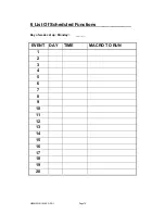
Page 65: ...ep a record of scheduled events for easy reference A table is provided in the back of this manual to list the scheduled events Remote Control RS 232 Remote Control RS 232 remote control is via a 9 way...

Page 66: ...Page 65 9 way Connector Figure 9 9 way Connector Numbering Pin Signal Function 1 not used 2 Rx Receive Data 3 Tx Transmit Data 4 not used 5 GRD Ground 6 not used 7 not used 8 not used 9 not used Tabl...

Page 67: ...video recordings On screen programming via menus settings retained when powered off Secure 1 hour adjustment for Summer Winter time without access to the menu system Inputs and Outputs 10 or 16 loop t...

Page 68: ...Events 10 or 16 alarm inputs each N O or N C on a 25 way D type connector max 100 ohm contact resistance Videoloss Detection Activity Detection Alarm Responses Interleaving or exclusive recording of a...

Page 69: ...level 0V Power Auto ranging 110 230V AC 10 50Hz to 12V DC external power supply provided Power Consumption Max 20W Physical Specifications Operational temperature limits 0 deg C to 40 deg C at 10 to 8...

Page 70: ...69 5 Function List MACRO DESCRIPTION 1 2 3 4 5 6 7 8 F Play VCR VIEW Selects the VCR as an input so that the VCR can be set up F SEQ SUMMER WINTER TIME Sets clock ahead 1 hour in March April and back...

Page 71: ...HBZMXSIB 10 16SD PR 1 Page 70 6 List Of Scheduled Functions Day of week set up Monday ______ EVENT DAY TIME MACRO TO RUN 1 2 3 4 5 6 7 8 9 10 11 12 13 14 15 16 17 18 19 20...

Page 72: ...SERVED 32 RESERVED 33 MON_B_KEY 34 CAMERA_POWER_KEY 35 WASH_KEY 36 AUTO_PAN_KEY 37 LIGHTS_KEY 38 WIPE_KEY 39 PRESET_KEY 40 FOCUS_FAR_KEY 41 FOCUS_NEAR_KEY 42 IRIS_CLOSE_KEY 43 IRIS_OPEN_KEY 44 ZOOM_IN...

Page 73: ...83 NETWORK_ADDRESS For command type DO 0 Reserved UPLOADING DATA BYTES When a message of type 0xBB is sent to the system it will respond by sending a 0xff start byte followed by the requested informa...

Page 74: ...r disable the display of the time and the date buffer 0 0xff buffer 1 0xAA buffer 2 1 buffer 3 DISPLAYTD buffer 4 BINARY number 0 disable 1 enable p Enable or disable the display of the titles buffer...

Page 75: ...t exceed 32 y Enable activity detection buffer 0 0xff buffer 1 0xAA buffer 2 16 buffer 3 ENACTIVITY buffer 4 buffer 19 BINARY list of 16 numbers digits 0 disable 1 enable z Request activity settings b...

Page 76: ...event number 0 99 b space character mm month dd day hh hours mm minutes ss seconds CR LF Carriage return line feed pair b Activity settings Six bytes are uploaded i Sensitivity 1 10 ii Relay 0 none 1...

Page 77: ...nd not it half resolution mode field display The half resolution mode is indicated on the monitor by the presence of the character to the left of the time and date display Press the camera 1 key to to...

Page 78: ...HBZMXSIB 10 16SD OP 1 Page 2 This page is intentionally blank...

Page 79: ...ng instructions for the ZMX BD 10 ZMX BS 10MD and ZMX CS 10 Multiplexers It does not include programming instructions which are provided in the Programming Instructions Manual Section 1 provides impor...

Page 80: ...HBZMXSIB 10 16SD OP 1 Page 4 This page is intentionally blank...

Page 81: ...Keys 16 ALARM key 16 FREEZE key 17 ZOOM key 17 Multi screen key 17 LIVE mode key 17 RECORD mode key 17 PLAY mode key 18 Adjusting the Picture Brightness and Contrast During Playback 19 FUNCTION key 1...

Page 82: ...lay Mode 30 Alarm Displays In Record Mode Simplex Models Only 30 Alarm Indicators 31 Alarm Latching 31 Videoloss 31 Selecting VCR As An Input VCR View 32 Summer Winter Time Change 32 Adjusting The VCR...

Page 83: ...the unit and to protect it from overheating these openings must not be blocked or covered This unit should not be placed in a built in installation unless proper ventilation is provided Do not place...

Page 84: ...titutions may result in fire electric shock or other hazards Safety Check Upon completion of any service or repairs to this unit ask the service technician to perform safety checks to determine that t...

Page 85: ...teries according to the manufacturers instructions WARNING Do NOT use the 12V power leads in the RS 485 cable UNLESS it is to be used on a one to one connection between a unit with 12V power and a uni...

Page 86: ...us With all of the models the front panel contains all the operator control keys and indicators while the video inputs video outputs alarm inputs and outputs and the remote control connectors are on t...

Page 87: ...e analogue output which cannot be frozen or zoomed Monitor B is sometimes referred to as a Spot monitor in the security industry The alarm inputs are normally associated with each of the cameras When...

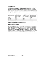
Page 88: ...impression of motion Normally a VCR would record every frame Multiplexing time division multiplexing as done by your multiplexer means that the camera signals are combined as a single signal from all...

Page 89: ...ith 10 cameras fields per second with 16 cameras 3 hour 50 5 3 125 12 hour 12 5 1 25 78 24 hour 6 25 625 39 48 hour 3 13 313 2 Table 1 Time lapse modes and recording quality Features of your Multiplex...

Page 90: ...l video processors and as a result it always has the multiplexed RECORD mode active in the background You can therefore choose LIVE or PLAY mode while the unit continues to record Record Mode RECORD m...

Page 91: ...ve full screen images during PLAY mode Only Monitor A displays playback images Live Mode There are several different multi screen display formats that can be selected by you on the Monitor A multi scr...

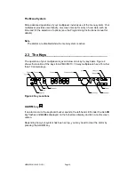
Page 92: ...while the menu system is active 2 3 The Keys The operation of your multiplexer is given below on a key by key basis Figure 4 shows the location of the keys for a ZMX CS 10 16 way multiplexers have 16...

Page 93: ...illuminated In a full screen display press the ZOOM key once to activate and again to deactivate In a multi screen display the first press changes the display to full screen press it again to zoom Use...

Page 94: ...ystem to change the speed on the Multiplexer PLAY mode key This key selects PLAY mode This key will not operate if your Multiplexer is locked in RECORD mode simplex models PLAY mode will always stop a...

Page 95: ...eras when you go back to multi screen The up arrow increases the brightness and the down arrow decreases the brightness The left arrow reduces the contrast and the right arrow increases the contrast F...

Page 96: ...system at any time and you will not lose your settings provided you have already selected OK where appropriate and pressed the ENTER key ENTER key This key makes selections in the MENU system MON B Ke...

Page 97: ...lexer you have you can switch your multi screen display between the following options using the multi screen key The individual areas of a multi screen are called cameos Multi screen Notes 16 WAY 4X4...

Page 98: ...same time format for the indicator as is generally used by time lapse VCRs For example R024 will be displayed to indicate that the unit is Recording in 24 hour mode If the VCR switch input is active t...

Page 99: ...e last multi screen format that was being viewed For example if you are viewing a 7 way multi screen and switches the display to a full screen display then if the MULTISCREEN key is pressed later the...

Page 100: ...y enter camera numbers in several cameos without using the arrow keys FREEZE key Freezes the cameo ZOOM key Switches to a full screen display of that camera This will cancel active cameo mode Note If...

Page 101: ...ight hand side of the display or else on the top left hand side of the display Changing The PIP Size And Position In LIVE Mode The PIP size and position can be changed during LIVE mode by using the ar...

Page 102: ...hite Bottom black Bottom grey Bottom white Do not display this camera title Top black repeats from top of list Note 1 This setting affects only the Monitor A display Text on the Monitor B display is n...

Page 103: ...This indicator warns you that the update rate is very slow or updating may have stopped It warns that there may have been events that were not captured during the recording or the tape data may be co...

Page 104: ...mera on tape have been corrupted and cannot be decoded at time of playback 4 The VCR play speed is very slow The not available indicator N A helps you to tell the difference between images which are n...

Page 105: ...ly switch to a full screen display of the camera in alarm If multiple alarms are active Monitor A will automatically sequence between the alarm cameras at a fixed 1 second dwell This dwell is not prog...

Page 106: ...a live alarm occurs during play mode then Monitor B will automatically switch to the camera in alarm It will sequence at a 1 second dwell time for multiple cameras in alarm After you have cancelled t...

Page 107: ...tor A multi screens whenever motion has been detected The indicator is not present on full screen analogue displays This motion indicator will stay on each active camera s display for at least 2 secon...

Page 108: ...put repeat the above procedure Note On simplex units this function is not available during RECORD mode Summer Winter Time Change To adjust the clock by an hour for Summer Winter time changes press the...

Page 109: ...t 2 8 Macro Functions Playing A Macro A macro can be played back simply by pressing the FUNCTION key F followed by the macro number Indicator While the macro is playing back Fn and the macro number ar...

Page 110: ...34 3 Function List MACRO DESCRIPTION 1 2 3 4 5 6 7 8 F Play VCR VIEW Selects the VCR as an input so that the VCR can be setup F SEQ SUMMER WINTER TIME Sets clock ahead 1 hour in March April and back 1...

Page 111: ...HBZMXSIB 10 16SD OP 1 Page 35 4 List Of Scheduled Functions Day of week setup Monday ______ EVENT DAY TIME MACRO TO RUN 1 2 3 4 5 6 7 8 9 10 11 12 13 14 15 16 17 18 19 20...

Reviews: