


601
–
426-03
F70 Series
104
8.5.2 Set up the system
How to set up the system
In this chapter, the setup procedure for the projectors is explained, but a setup procedure must also be
performed for the picture source.
In order to obtain a satisfying result for the Blend function, the overlap / Blend zone are
recommended to be at least 10% of the picture width.
The basic principle is that the overlap setup in the source shall correspond with the blend width setup for the
projector. That means that if the overlap zone for the source is set to 500 pixels, the width of the blend zone for
the projector also must be set to 500 pixels.
First step is to align the image from the projectors as accurate as possible in a mechanical way, meaning
without any optical corrections. At the same time, establish an overlap in the pictures between the two
screens.
Then adjust the remaining irregularities by using the shift and warp features in the projectors to obtain the last
fine tuning of the alignment.
Setup the source to a blend which corresponds with the preset overlap on the screen. There are different ways
to do this, depending on the source. Refer to the source unit's manual for this issue.
Adjust the Blend for the projectors as described below.
8.5.3 Adjustment Procedure
Blend adjustment procedure
Entering the Blend Adjustment from the Home menu, either by the remote control, or the keypad on the
projector.
Home/Installation/Blend And Mask/Blend Mask
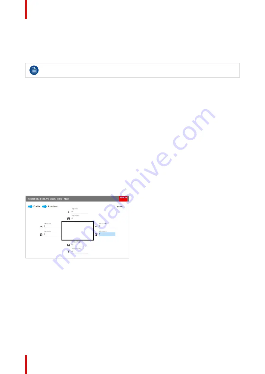
The menu shown below appears on the OSD.
The
“
Enable
”
button enables/disables the blend function. The
“
Show Lines
”
enables alignment lines on the
screen, in order to visualize the overlap/blend zone.
Image 8-40: Blend adjust menu
Use the up/down/left/right arrow key on the remote control or key pad to navigate in the menu.
Blend adjustment procedure. Side by side configuration.
1.
Starting with the left picture: By the arrow keys, place the display cursor on respectively the
“
Enable
”
zone and
the
“
Show Lines
”
zone and activate them by pressing enter.
2.
Use the right arrow key to move the cursor to the
“
Top Mask
”
position in the menu. Press enter. From this
position the cursor can be moved around to the desired adjustment options.
3.
Move the cursor to the
“
Right Width
”
position and press enter on the remote control.
4.
Adjust the width value by using the arrow keys up (or down), one step at a time. By pressing the key arrow
constantly, the blend value will increase rapidly. The numeric value of the width is shown on the screen next to
the alignment line. (The number entered represent the blend width expressed in number of pixels). Confirm
position by pressing enter.
Summary of Contents for F70 - 4K6
Page 1: ...ENABLING BRIGHT OUTCOMES User Manual F70 Series...
Page 8: ...601 426 03 F70 Series 8 14 3 FS70 4K6 132 14 4 FS70 W6 134...
Page 26: ...601 426 03 F70 Series 26 Safety...
Page 38: ...601 426 03 F70 Series 38 Getting to know the projector...
Page 46: ...601 426 03 F70 Series 46 Lenses...
Page 68: ...601 426 03 F70 Series 68 Getting started...
Page 74: ...601 426 03 F70 Series 74 Source menu...
Page 76: ...601 426 03 F70 Series 76 Image 7 2 Image sub menu visible on the LCD Image menu...
Page 120: ...601 426 03 F70 Series 120 Status menu...
Page 124: ...601 426 03 F70 Series 124 3D...
Page 125: ...125 Overview Update Projector Firmware 601 426 03 F70 Series User Maintenance 12...
Page 127: ...127 601 426 03 F70 Series Cleaning the projector 13...


