www.baldormotion.com
5-22 Operation
MN1941
5.6 Local stepper axis - testing
This section describes the method for testing a local stepper axis. The stepper control is an open
loop system so no tuning is necessary. See section 5.5.3 for details about creating a stepper
axis.
5.6.1 Testing the output
This section tests the operation and direction of the output. It is recommended that the system is
initially tested with the motor shaft disconnected from other machinery.
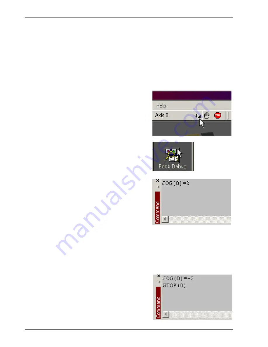
1. Check that the Drive enable button is
pressed (down).
2. In the Toolbox, click the Edit & Debug icon.
3. Click in the Command window.
4. Type:
JOG(0)=2
where 0 is the axis to be tested and 2 is the
speed.
The
JOG
command specifies the speed in
user units per second, so the speed is
affected by
SCALEFACTOR
(section 5.5.4). If you have not selected a scale, the
command
JOG(0)=2
will cause rotation at only 2 half steps per second, so it may be
necessary to increase this figure significantly, to 200 for example. If you have selected
a scale that provides user units of revolutions (as described in section 5.5.4),
JOG(0)=2
will cause rotation at 2 revolutions per second. If there appears to be no step or direction
output, check the electrical connections to the axis’ assigned STEP
x
and DIR
x
outputs.
5. To repeat the tests for reverse moves, type:
JOG(0)=-2
6. To remove the demand and stop the test, type:
STOP(0)
Summary of Contents for NXE100-1608Dx
Page 1: ......
Page 2: ......
Page 16: ...www baldormotion com 3 4 Basic Installation MN1941 ...
Page 50: ...www baldormotion com 4 34 Input Output MN1941 ...
Page 77: ...www baldormotion com Operation 5 27 MN1941 Figure 37 The NextMove e100 servo loop ...
Page 98: ...www baldormotion com 6 8 Troubleshooting MN1941 ...
Page 110: ...Index MN1941 ...
Page 112: ...Comments MN1941 Thank you for taking the time to help us ...
Page 113: ......
Page 114: ......


