DESCRIPTION AND OPERATION
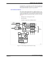
SAC STATION I/O CIRCUITRY
2 - 18
I-E96-117B
®
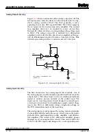
Analog Output Circuitry
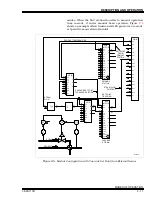
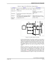
Figure
shows a schematic of the analog output circuit. The
microprocessor sends the desired control output value to a dig-
ital to analog converter (DAC). The DAC generates a corre-
sponding zero to five VDC signal (VDAC). The VDAC signal is
the set point for the current loop error amplifier. The current
loop amplifier drives Q1 as required to cause current flow
through R1 which develops a corresponding voltage drop equal
to VDAC. The voltage across R1 is buffered by a differential
amplifier and is routed to the current error amplifier as the neg-
ative feedback signal required to form a closed servo loop. This
closed loop system provides a constant current to the load.
Analog Input Circuitry
The SAC station has two analog inputs (AI) available. One of
the analog inputs usually monitors position feedback from the
output device. The other input can be an additional feedback
signal or another process variable in the control loop. The
input can be a system powered current input, externally pow-
ered input current (four to 20 milliamps), single ended voltage
(one to five VDC) or differential voltage. Dipshunt settings on
the TCS termination unit set the input type.
The analog input circuit prepares the analog signal and makes
it compatible with the microprocessor. It first passes through a
60-hertz filter, high impedance buffer amplifier, and differen-
tial amplifier. The output of the differential amplifier passes
through an error compensation circuit. This circuit takes the
0.75 to 5.25 VDC input and changes it to a corresponding zero
Figure 2-10. Analog Output Circuitry
VDAC
ERROR AMP
DIFF AMP
24 VDC
Q1
R1
(SEE NOTE)
D1
LOAD
(0-600
)
Ω
T00295A
NOTE: DIODE D1 CORRESPONDS TO D1
IN FIGURE 2-8.

