


DESCRIPTION AND OPERATION
SYSTEM OPERATION
2 - 2
I-E96-117B
®
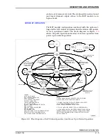
process variable (PV), set point (SP) and control output (CO) are
displayed on the SAC station faceplate.
The SAC station control functionality is contained in the MFP
module configuration. The control station function code (func-
tion code 80) determines the type of station (basic, cascade, or
ratio) and other operating parameters. The SAC station pro-
vides the operator interface. This interface includes:
•
Bar graphs.
•
Pushbuttons.
•
Annunciators.
•
Alphanumeric displays.
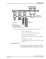
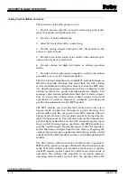
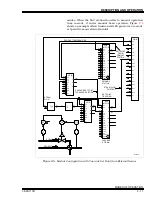
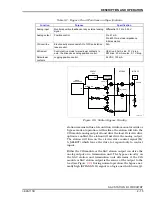
Figure 2-1. SAC Station Application Example
I/O EXPANDER BUS
T00287A
MFP
CIS
TCS
TMP
SAC
PROCESS
I/O
SIGNALS
CONTROLWAY
LEGEND:
CIS = CONTROL I/O MODULE
MFP = MULTI-FUNCTION PROCESSOR MODULE
SAC = ANALOG CONTROL STATION
TCS = CONTROL I/O TERMINATION UNIT
TMP = MULTI-FUNCTION PROCESSOR MODULE
TERMINATION UNIT
RS-485 SERIAL
LINK AND
4-20 mA I/O
RS-485
SERIAL LINK
RS-485
SERIAL LINK
4-20 mA I/O


