INSTALLATION
MICROCOMPUTER MODE OF OPERATION (JP3)
I-E96-117B
3 - 11
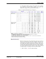
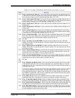
When the station exits electric drive bypass mode to normal
mode operation, the new control output value is the value of
the analog input as defined in Tables
. At the time
of transfer, either AI1 or AI2 becomes the control output in
normal mode. Normally, AI1 is the position feedback from the
device and AI2 is the process variable.
MICROCOMPUTER MODE OF OPERATION (JP3)
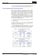
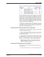
Microcomputer mode of operation jumper settings determine
the internal configuration of the microprocessor. Factory tech-
nicians use this option setting during factory testing of the sta-
tion; do not use it during normal operation. For normal
operation, JP3 must be shorted across pins one and two. Table
shows the jumper settings for this option.
MOUNTING THE STATION HOUSING
The housing for the SAC station is designed for conventional
panel board mounting. The housing fastens securely in a panel
with thickness ranging from 0.09 to 1.00 inch. Multiple side by
side stations can mount in a single panel opening. To install
the station housing:
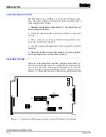
1. See Figure
for the station housing panel cutout and
mounting dimensions. Prepare the panel opening accordingly.
2. Insert the housing through the panel opening until the
front flange is in contact with the panel.
3. While holding the flange flush with the panel, rotate each of
the 2 retaining clip screws counterclockwise to allow the clips
to clear the thickness of the panel, then clockwise until the
clips are snug against the back of the panel. Be careful not to
over tighten the retaining clip screws.
4. Insure that the housing is secure.
NOTE: Do not install a SAC station in its housing until all of the
appropriate cable connections are made. When replacing the
NDCS03 station with the IISAC01 station, use the station housing
that accompanies the SAC station. The SAC station does not fit into
the DCS station housing. Additionally, use of the second analog
input available with the SAC station requires replacement of the ter-
mination unit and termination cables. Both analog inputs are avail-
able on the NTCS04 Control I/O Termination Unit. Replace the
cables with NKCS01 and NKCS02 cables.
Cable Lengths
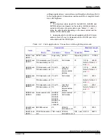
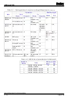
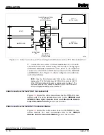
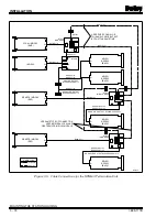
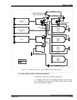
The station can be connected into a system with an NTCS04
termination unit and control station (KDS or KCS) cables. The
NTCS04 termination unit routes two analog inputs to the SAC

