background image


19 

19 

INTENDED USE 

Table saw and the workpiece guide equipment supplied with it are intended to be used 
exclusively for the following purposes: 

  Laminated and unlaminated board materials (e.g. chipboard, coreboard, MDF board, ...) 

  Solid wood 

  Gypsum plasterboard, Cardboard, Veneer with a suitable clamping device. 

  Dimensionally stable plastics (thermoset plastics, thermoplastics). Sawing these materials 

does not normally involve any risks in respect of dust, chips, and thermal degradation 
products. 


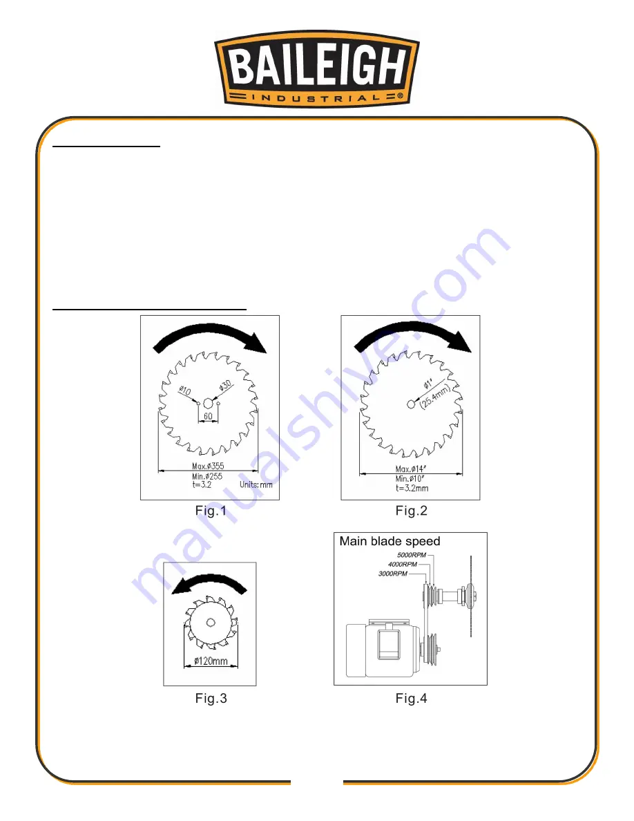
OPERATIONAL INDICATION 


Fig. 1: the main saw's size and running direction. 
Fig. 2: the main saw's size and running direction. 
Fig. 3: the scoring saw's size and running direction. 
Fig. 4: Belt speed diagram. 

Summary of Contents for STS-14120DRO

Page 1: ...ITED Baileigh Industrial Inc does not assume and hereby disclaims any liability for any damage or loss caused by an omission or error in this Operator s Manual resulting from accident negligence or ot...

Page 2: ...TTING EXTENSION TABLE INSTALLATION 25 CROSSCUT TABLE ASSEMBLY 26 CROSSCUT FENCE ASSEMBLY 27 Crosscut Fence Adjustment 27 Crosscut Fence Scale Adjustment 28 RIP FENCE ASSEMBLY 29 Rip Fence Adjustment 3...

Page 3: ...INTENANCE 72 Cleaning 72 Lubrication 73 Sliding Table Maintainance 73 Angle Slide Rail Maintenance 73 TROUBLESHOOTING 74 MAIN CABINET PARTS DIAGRAM 75 Main Cabinet Parts List 77 SUPPORT ARM PARTS DIAG...

Page 4: ...List 102 CROSSCUT FENCE TWO DIGITAL DISPLAY PARTS DIAGRAM 103 Crosscut Fence Two Digital Display Parts List 104 MITER FENCE PARTS DIAGRAM 106 Miter Fence Parts List 106 DUST COLLECTING FASTENING RACK...

Page 5: ...e to Seller of any suspected defect in the Goods prior to the expiration of the warranty period The original end user must also obtain a RGA from Seller prior to returning any Goods to Seller for warr...

Page 6: ...urther remedies provided under this Agreement or at law or equity Attorney s Fees In the event legal action is necessary to recover monies due from Buyer or to enforce any provision of this Agreement...

Page 7: ...tion of the functional parts of the machine Capacity charts Set up and start up instructions Machine operation Scheduled maintenance Parts lists GENERAL NOTES After receiving your equipment remove the...

Page 8: ...es a hazard or unsafe practice that will result in severe Injury or Death Safety signs with signal word DANGER or WARNING are typically near specific hazards General precautions are listed on CAUTION...

Page 9: ...birth defects and long term respiratory damage Be aware of the dust hazards associated with all types of materials DUST PARTICLES AND IGNITION SOURCES DO NOT operate the table saw in areas where expl...

Page 10: ...safety precautions are overlooked or ignored personal injury to the operator may result Safety equipment such as guards push sticks hold downs feather boards goggles dust masks and hearing protection...

Page 11: ...es 10 Push Sticks and Push Blocks When ripping narrow stock there is a risk of your hands 11 and fingers contacting the rotating blade resulting in serious personal injury Overloading machine By overl...

Page 12: ...a cut Supporting Piece Part Provide adequate support to the sides and rear of the saw table for 27 material that is extra wide and long Keep visitors a safe distance from the work area 28 Keep childr...

Page 13: ...arning The dust generated by certain woods and wood products can be injurious to your 39 health Always operate machinery in well ventilated areas and provide for proper dust removal Use a wood dust co...

Page 14: ...ines and other adjacent processes Also the permissible exposure level can vary from country to country this information however will enable the user of the machine to make a better evaluation of the h...

Page 15: ...e Bore 875 22mm Scoring Motor Power 1hp 0 75kw Scoring Blade Speed 8000 rpm Cutting Width 39 3 1000mm Cutting Width Adjustment Manual Saw Table Extension 14 5 370mm Blade Titing Adjustment Manual 0 45...

Page 16: ...78lbs 157 217kg 412 545lbs 187 247kg TECHNICAL SUPPORT Our technical support department can be reached at 920 684 4990 and asking for the support desk for purchased machines Tech Support handles quest...

Page 17: ...Diameter range and thickness are both engraved at the bottom end of the riving knife The thickness of the riving knife was selected so that they match the commercially available saw blade thickness i...

Page 18: ...h no visible damage and be able to support the machine s full gross weight to prevent breakage Use Lift Truck To Move Woden Crate Place the wooden crate in the middle of the forks and keep at least 2...

Page 19: ...arance zone around the transport area The machine is equipped with the slots that are specially designed for transport of lift truck and manual electric trolley Use Gantry Or Crane To Move Machine Fig...

Page 20: ...y take note of the following precautions and suggestions The machine is bolted to the pallet Before attempting any of the assembly procedures remove all of the loose parts and hardware from the inside...

Page 21: ...17 17 Clearance Dimensions A 126 3200mm B 33 5 850mm C 59 1500mm D 68 1725mm E 71 75 1820mm F 127 3230mm maximum G 138 75 3525mm H 136 5 3470mm...

Page 22: ...o remove this protective coating use a degreaser or solvent cleaner For a more thorough cleaning some parts will occasionally have to be removed DO NOT USE acetone or brake cleaner as they may damage...

Page 23: ...plasterboard Cardboard Veneer with a suitable clamping device Dimensionally stable plastics thermoset plastics thermoplastics Sawing these materials does not normally involve any risks in respect of d...

Page 24: ...ling Panel Control the machine s running indication stop etc F Miter Fence Reference positioning while 0 45 cutting G Main Saw Tilting Adjusting Hand Wheel Hand wheel for adjusting main saw tilting 0...

Page 25: ...g INITAIL INSTALLATION ASSEMBLY Verify that the saw is positioned in the desired 1 location Verify that the leveling feet are properly positioned 2 under the leveling bolts and that the table is level...

Page 26: ...for tilting the blade Note Use care when placing the sliding table on the contact surfaces so as not to damage the surfaces The sliding table may require from 4 6 workers to lift safely Using the ass...

Page 27: ...table to the machine just enough to allow movement 8 for adjustment Use the 2 adjusting screws at the ends of the main 9 cabinet to make the sliding table parallel to the saw blade and keep the gap wi...

Page 28: ...caps on the ends of the slide table 17 Remove the bolts from the slide table and insert the bolts through the end cap brackets and tighten The end cap with the handle go on the right end of the slidi...

Page 29: ...bolts so 5 that the extension is tight to the main table and the washers and bolt heads C are to the inside of the extension table Install the leveling bolt locating bolts D into the 6 extension tabl...

Page 30: ...horter aluminum channel E on the crosscut table with the bar clamp positioned to clamp the channel in place Tighten the bar clamp bolts D to secure the channel 7 The longer channel F is a movable chan...

Page 31: ...main table and the locating pins into the positioning points B and C of the crosscut table Lift the lock handles D and slide 2 them inward to the fully unlocked position Set the locating pins of the c...

Page 32: ...ard in the sequence shown 10 cutting from NO 1 5 Measure diagonally across the the board to check if 11 the board is square If the board is not square adjust the crosscut fence cam as noted in steps 5...

Page 33: ...ht as the direction shown in the above drawing Parallelism of the sliding table and the main saw blade must be adjusted within tolerance before proceeding Adjust the eccentric wheel on the front end o...

Page 34: ...target size Loosen knob B 2 Turn the micro knob C to the target size 3 Turn the micro knob clockwise direction 4 movement Turn the micro knob counter clockwise direction 5 movement To fasten the rip f...

Page 35: ...liding table slot and tighten until the miter fence is snug but will rotate on the pivot bolt Swing the miter fence to the desired angle and 4 tighten the clamp handle A Note Swing the miter fence slo...

Page 36: ...electrically conductive hoses only Delux Saw Guard Install the dust collection support rack onto the left side of the machine as shown in above 1 drawing Before installing the safety guard lower the...

Page 37: ...e is 1220 1390 m hr 43 000 49 000 cu ft hr Use antistatic and electrically conductive hoses only Two dust collecting outlets are available on the machine to assist with dust removal The saw guard has...

Page 38: ...y under the saw table 2 Push up on the saw guard lock button to loosen the 3 saw blade shield and move backward to remove Fig 1 Fig 2 Note While cutting workpiece At 90 cutting 90 special safety guard...

Page 39: ...riving knife to 3 move Adjust the 3 set screws B at the sides of the retaining screws as the projected place shown 4 in the above drawing Measure the relative size of the riving knife and saw blade 5...

Page 40: ...s are dangerously sharp Use extreme caution when working with or around the blade Wear proper safety protection such as heavy gloves WARNING Turn the power switch OFF and unplug the power cord from it...

Page 41: ...to the spindle fixing hole 6 Loosen the nut clockwise clean the flange and new saw blade and then install them onto 7 the spindle Important The main saw blade flange nut must be torqued to 21 7 lb ft...

Page 42: ...A press 3 down on handle B to raise the motor Lift the rotating speed knob upwards 4 Change the rotating speed knob and belt as per the motor s rotating speed list Then push 5 the handle upwards to ma...

Page 43: ...on Clockwise increases the tilt angle Counterclockwise decreases the tilting angle C Hand wheel lock knobs After adjusting the hand wheel lock up the knob to secure the blade in position for accuracy...

Page 44: ...ove the slide table back to the right to engage the 9 travel limit rod Important The scoring saw blade flange nut must be torqued to 20 lb ft 250kg cm The shims are used to adjust the cutting width of...

Page 45: ...esult in risk of electric shock The conductor with insulation having an outer surface that is green with or without yellow stripes is the equipment grounding conductor If repair or replacement of the...

Page 46: ...nduction unit to circuit 0V or GND 4 Sensor shielded cables please direct connection to the controller 5 For reducing controller interference Use separate signal wire and power wire 6 The programmable...

Page 47: ...shown in the Fig 1 and Fig 3 3 Connect the earth wire green yellow to PE terminal Start motor to check if the rotating direction of the main saw blade and the scoring saw is as 4 shown in Operational...

Page 48: ...h outside of this manual by reading how to books trade magazines or websites To complete a typical operation the operator will Examines the workpiece to make sure it is suitable for cutting 1 Adjusts...

Page 49: ...If the machine starts the emergency stop is not operating properly immediately stop operation Have someone trained in electrical circuits inspect and test the system and possibly replace the emergenc...

Page 50: ...on 5 Set button 6 Set button Notes The angle screen of the machine adopts micro computer single chip controller so it is stable and safe under long term use When power is off the angle screen does not...

Page 51: ...47 47 CORRECTING CURRENT DIMENSION The figure shows 21 5 on the display If for example the correct position is 35 1 The following steps will change and set the correct position...

Page 52: ...set the new pararmeter Notes The operators must pay attention not to make any change Otherwise the controller operation may be unusual and damaged the machine Unless you are and authorized technician...

Page 53: ...ient setting Low battery alarm Parameters stored in permanent memory Correct zero point Absolute relative conversion Inch mm conversion Fine adjustment Real time self diagnose Specifications 8 digits...

Page 54: ...50 50 ABS REL Definition ABS absolute REL incremental Front Panel and LCD Display 4 000mm 2 000mm 1 000mm Zero point 0 mm Zero point 0 mm 2 000mm 1 000mm 1 000mm...

Page 55: ...51 51...

Page 56: ...52 52 Load Datum Values Only In ABS Mode A Description...

Page 57: ...53 53...

Page 58: ...54 54 B Load Datum...

Page 59: ...55 55 C Troubleshooting...

Page 60: ...56 56 Select Counting Direction...

Page 61: ...57 57...

Page 62: ...58 58 Set Device Resolution...

Page 63: ...59 59...

Page 64: ...60 60 Enable and Disable Specified Parameter...

Page 65: ...61 61...

Page 66: ...62 62...

Page 67: ...d datum value 0 2 dir Select counting direction dir 3 Off SETS Set tool diameter 0 4 ANGULAR Enter semi diameter value 0 5 SCALING Diameter semi diameter Ad 6 Lin Corr Linear correction 1 00000 7 SETU...

Page 68: ...64 64 Parameter Setting...

Page 69: ...el tape A and B are already factory bonded To keep the flexibility for transport and installation the third part C also a steel tape is delivered separately It serves for mechanical protection of the...

Page 70: ...current wires 2 Must be kept a distance to interference sources 3 Ensure to apply tape on clean dry and plain surface 4 For the best adhesion please apply the tape with ambient temperature 70 100 F 5...

Page 71: ...67 67 External Dimension Mounting Installation 10...

Page 72: ...68 68 Appendix B Calibration A For better accuracy calibrate for the first time installation or if the slider has been reinstalled Gap 1 2 5mm Recommended 1mm Gap about 1mm...

Page 73: ...69 69...

Page 74: ...70 70 B Troubleshooting...

Page 75: ...71 71...

Page 76: ...ge To minimize the risk of electric shock or fire never operate the saw with a damaged power cord Replace a damaged power cord at the first sign of damage To minimize airborne dust particles periodica...

Page 77: ...ld smooth moving components ISO DIS 3498 Lubricating Cycle Lubricating Way XM2 6 months Lubricate the machine BRAND MOBIL ESSO SHELL MOBILUX 2 BEACON 2 ALVANIA R2 Sliding Table Maintainance Clean the...

Page 78: ...l size Check if parameter is correct Contact the manufacturer to get correct parameter LED displays normally but LED value does not react when angle moves Check if spindle connecting device between en...

Page 79: ...75 MAIN CABINET PARTS DIAGRAM CE TYPE 011 012 012 011 009 008 007 006 013 014 016 017 015 018 019 002 004 005 075 076 079 078 077 075 081 084 085 083 074 075 080 081 083 CE TYPE 003 001 008 007 006 0...

Page 80: ...28 036 035 037 028 036 049 060 062 061 063 065 067 050 058 059 057 056 054 053 055 052 051 066 064 063 068 033 033 042 048 047 040 039 041 043 086 034 046 044 045 016 016 027 026 025 087 021 020 001 0...

Page 81: ...Phillips Head Screw M5 x 8 057 Phillips Head Screw M4 x 8 014 Washer 5 058 Gear 015 Washer 6 059 Setscrew M6 x 6 016 Lock Washer 6 060 Adjust Base BD 100 017 Button Head Screw M6 x 10 061 Hex Nut M16...

Page 82: ...Cap Screw M6 x 16 036 Thrust Bearing 51102 080 Cap Screw M4 x 10 037 Bearing Base 081 Safety Switch EK 1 15 R 038 Key 5 x 5 x 15 082 Cap Screw M5 x 12 039 Washer 083 Lock Washer 4 040 Cap Screw M6 x...

Page 83: ...79 79 SUPPORT ARM PARTS DIAGRAM 001 002 003 004 005 007 016 017 015 012 016 007 014 011 013 010 011 010 012 005 007 007 008 009 009 002 001 003 015 018 018 019 020 021 018 023 018 019 022 006 025 024...

Page 84: ...008 Position Shaft 009 Ball Bearing 6203 LLU 010 Retain Ring STW 17 011 Ball Bearing 6003 ZZ 012 Sliding Wheel 013 Adjust Shaft 014 Washer M8 015 Retain Ring STW 15 016 Ball Bearing 6202 ZZ 017 Slidin...

Page 85: ...008 014 013 038 011 010 008 009 016 015 015 016 012 013 014 010 008 009 008 037 017 019 018 010 009 008 020 012 013 014 022 021 024 023 017 032 029 034 CE TYPE 001 002 003 004 005 031 035 036 035 036...

Page 86: ...16 008 Lock Washer 8 028 Sensor TZ 7311 009 Hex Head Bolt M8 x 25 029 Washer 4 010 Washer 8 x 23 030 Phillips Head Screw M4 x 30 011 Fixed Block 031 Safety Switch EK 1 15 R 012 Adjust Shaft 032 Cap Sc...

Page 87: ...DIAGRAM 015 016 017 010 018 019 020 021 022 024 023 025 026 027 032 030 031 001 002 003 006 004 007 008 009 011 014 012 013 010 005 034 028 029 013 036 035 024 037 038 039 040 041 042 043 044 045 002...

Page 88: ...ead Screw M6 x 12 009 Fixed Block 034 Setscrew M10 x 16 010 Cap Screw M5 x 16 035 Fixed Sheet 011 Fixed Block 036 Hex Head Bolt M6 x 12 012 Cap Screw M6 x 20 037 Bearing Cover 013 Lock Washer 6 038 Be...

Page 89: ...LT PARTS DIAGRAM 035 036 037 038 039 040 039 041 042 006 043 013 012 013 014 012 003 002 001 008 006 005 004 007 009 010 011 028 029 030 032 033 034 031 032 016 017 024 026 023 022 027 018 020 006 021...

Page 90: ...bricant Plug 45 M6 x 10 031 Washer 009 Driving Nut 032 Thrust Bearing 51103 010 Join Shaft 033 Worm 011 Setscrew M8 x 6 034 Spacer 012 Cap Screw M10 x 25 035 Lock Washer 8 013 Lock Washer 10 036 Cap S...

Page 91: ...7 009 010 011 012 014 013 014 015 015 016 015 014 013 013 018 017 015 014 013 015 013 019 019 020 016 017 021 022 023 025 024 026 031 030 029 028 027 034 032 033 063 036 035 038 039 040 041 042 053 05...

Page 92: ...iding Rail 43 Spindle Base 13 Fixed Ring 44 Spacer 14 Washer 45 Waves Spring 15 Setscrew M5 x 4 46 Spacer 16 Sliding Block 47 Pulley 17 Sliding Block 48 Fixed Ring 18 Bush MB1220 49 Lock Washer 8 19 B...

Page 93: ...R PARTS DIAGRAM 023 006 007 021 020 019 021 019 024 022 021 020 019 017 018 016 002 001 004 003 013 007 006 005 010 009 008 037 035 036 033 020 034 031 019 033 028 026 030 027 025 026 019 012 032 008...

Page 94: ...Handle 95KA M12 0 007 Lock Washer 6 026 Washer 12 008 Setscrew M6 x 6 027 Spring Pin 6 x 32 009 Position Ring 028 Setscrew M12 x 50 010 Fixed Base 029 Lock Washer 6 011 Setscrew M12 x 50 030 Lock Nut...

Page 95: ...20 011 Pivot Axis 003 Washer 012 Stop Board 004 Belt 15 x 690 x 1 8t 013 Cap Screw M8 x 16 005 Countersink Head Screw M6 x 16 014 Washer 12 006 Fixed Ring 015 Lock Washer 12 007 Pulley 016 Hex Head B...

Page 96: ...x 120 Scale Base 1 5m 005 Hex Nut M16 015 Countersink Head Screw M6 x 35 006 Washer M16 016 Washer M6 007 Emboss Screw 017 Scale 1m 008 Fixed Block Scale 1 3m 1 5m 009 Cap Screw M6 x 16 Scale 1 3m 1...

Page 97: ...95 050 049 045 046 047 048 060 058 035 064 063 065 066 062 061 069 071 068 068 072 067 070 081 081 082 082 081 083 078 077 077 073 071 074 075 062 076 030 016 028 028 020 032 033 034 011 010 009 008 0...

Page 98: ...Fixed Base 010 Bristle Brush 061 Slide Bar 1 9m 011 Bristle Brush Base Slide Bar 2 6m 012 Lock Nut M8 Slide Bar 3 2m 013 Button Head Screw M6 x 16 062 Retain Ring STW 12 014 Adjust Block 063 Pull Bar...

Page 99: ...085 Support Scaffold 038 Stop Block 086 Hex Head Bolt M8 x 35 039 Cap Screw M4 x 10 087 Countersink Head Screw M8 x 25 040 Handle 088 T Shape Block CE 041 Button Head Screw M6 x 20 089 Stop Board CE...

Page 100: ...6 96 CROSSCUT TABLE PARTS DIAGRAM 001 003 001 002 001 001 005 006 008 009 010 011 012 007 006 005 004 028 029 013 015 014 016 017 018 019 020 021 022 026 025 023 024 030 029 028 032 029 031 033 033 02...

Page 101: ...ust Block 024 Fixed Shaft 008 Clamp Element 025 Crosscut Table 2 6m 3 2m 009 Countersink Head Screw M8 x 12 Crosscut Table 1 9m 010 Screw 026 Handle 011 Setscrew M6 x 10 027 Roller M8 x 15 012 Fixed S...

Page 102: ...1 5m 003 Hex Head Bolt 013 Hex Nut M16 004 Hex Head Bolt M8 x 20 014 Washer 12 005 Washer 8 015 Square Pipe Plug 40 x 80 x 3t 006 Washer 8 016 Setscrew M16 x 35 007 Washer 017 Width Extension 1m 008...

Page 103: ...ARTS DIAGRAM 005 006 004 003 007 008 002 001 041 014 017 019 018 014 016 019 018 008 007 011 021 022 020 023 015 012 013 024 025 026 027 031 032 033 028 030 029 009 034 035 036 038 038 039 040 039 038...

Page 104: ...g STW 18 009 Handle 1162 M12 125 031 Fixed Shaft 010 Fixed Shaft 032 Lockring 011 Retain Ring STW 20 033 Retain Ring STW 14 012 Setscrew M5 x 10 034 Hex Head Bolt M8 x 16 013 Control Knob 7021 40 B12...

Page 105: ...047 048 017 018 049 042 041 040 043 039 019 038 037 036 027 051 050 055 001 002 003 004 009 011 008 007 006 005 013 014 015 016 010 019 020 022 004 017 018 003 012 021 024 023 026 025 027 032 033 034...

Page 106: ...ashing Plate 038 Cap Screw M6 x 30 013 Countersink Head Screw M5 x 12 039 Fixed Stand 014 Fixed Ring 040 Lock Washer 5 015 Guide Wheel 041 Digital Display 50cm 016 Hex Head Bolt 042 Hex Nut M3 017 But...

Page 107: ...04 003 001 002 012 011 010 001 014 015 016 017 018 019 020 021 022 023 024 025 026 027 028 029 031 030 032 033 035 034 036 048 002 021 020 022 026 023 016 017 018 037 019 036 034 035 033 032 038 039 0...

Page 108: ...ic Ruler 061 Fixed Sheet 6 x 25 x 15L 014 Fixed Board 062 Spring Pin 6 x 40 015 Fixed Rack 063 Position Pin 016 Cap Screw M5 x 8 064 Cover 017 Lock Washer 5 065 Wooden Screw 1 8 x 3 4 L 018 Washer 5 0...

Page 109: ...de Base 085 Tightening Base 039 Lock Washer 5 086 Handle 7108 M10 100 040 Lock Washer 5 087 Rotary Fastening Base 041 Cap Screw M5 x8 088 Embossing Screw 042 Cap Screw M3 x 18 089 Hex Nut M6 043 Lock...

Page 110: ...004 Gap Ring 005 Setscrew M10 x 60 006 Locking Bushing 007 Washer 008 Square Insert 009 Displacement Pipe 010 Adjust Handle DA7012 A10 011 Setscrew M10 x 40 012 C Fastening Block 013 Lock Nut M8 014...

Page 111: ...st Block 002 Fixed Base 1m 010 Setscrew Fixed Base 1 3m 011 Cap Screw M8 x 16 Fixed Base 1 5m 012 Lock Washer 8 Fixed Base 400type 1m 013 Hex Nut M8 Fixed Base 400type 1 3m 014 Setscrew M8 x 25 Fixed...

Page 112: ...rts List Item Description Specs 001 Rotary Arm 1m Rotary Arm 1 3m Rotary Arm 1 5m 002 Connect Block 003 Bush 004 Cap Screw M8 x 16 005 Lock Shaft 006 Fixed Block 007 Knob 7083 710 M8 008 Lock Washer 8...

Page 113: ...27 017 030 031 022 020 019 036 032 034 045 035 049 014 040 034 037035 048 034 026 016 018 023 001 002 003 004 005 043 042 041 050 029 033 044 006 007008009007 010 006 013 005 012 038025034024 015 039...

Page 114: ...er 6 x 16 011 Button Head Screw M4 x 8 037 Washer 8 x 23 012 Chip Guard Cover 038 Button Head Screw M6 x 30 013 Grip Cover Base 039 Countersink Head Screw M6 x 12 014 Cap Screw M6 x 30 040 Spring 015...

Page 115: ...111 111 NOTES...

Page 116: ...INC 1455 S CAMPUS AVENUE ONTARIO CA 91761 PHONE 920 684 4990 FAX 920 684 3944 BAILEIGH INDUSTRIAL LTD UNIT 1 FULLWOOD CLOSE ALDERMANS GREEN INDUSTRIAL ESTATE COVENTRY CV2 2SS UNITED KINGDOM PHONE 44...

Reviews: