40
40
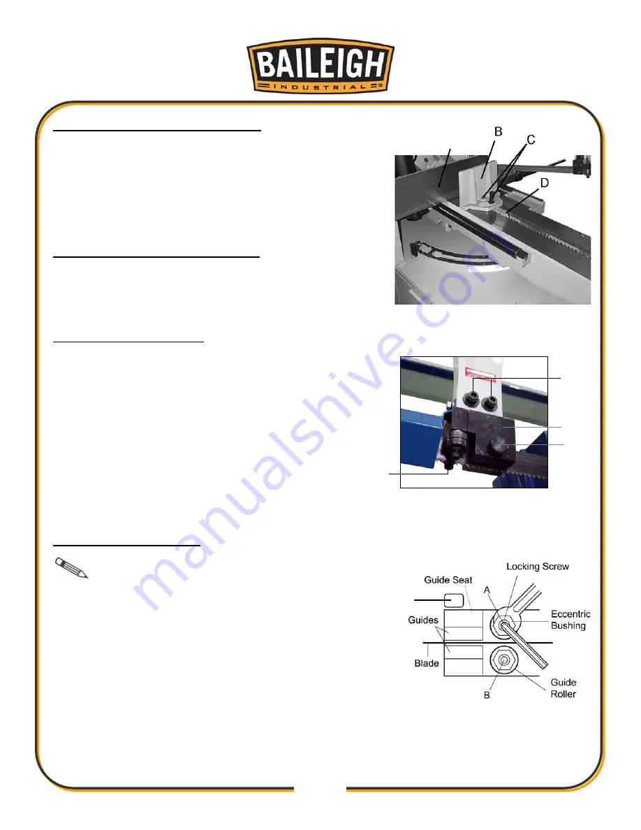
To adjust the angle of the vise jaw:
1. Loosen bolts (C)
2. Adjust the smaller movable vise jaw by rotating it.
3. Slide vise jaw (B) flush to fixed vise (A) to match
parallels.
4. Once parallel tighten bolts (C), then set position.
Setting the position of the vise jaw
1. Pull up on the rack block (D).
2. Move vise to desired location by sliding along table.
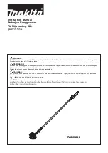
Thrust Roller Adjustment
1. Disconnect machine from the power source.
2. Loosen two hex socket cap screws (A).
3. Move guide seat (D) up or down until a clearance
of .003" to .005" (.08 - .13mm) between back of
blade and thrust roller is obtained.
4. Tighten two hex socket cap screws (A).
5. Repeat for other blade guide assembly.
6. Connect machine to the power source.
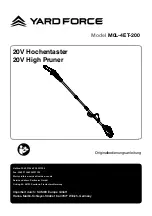
Guide Roller Adjustment
Note:
Only bearing (A) is adjustable. Bearing
(B) is fixed.
1. Disconnect machine from the power source.
2. Loosen blade guides by loosening guide adjustment
screw (C).
3. Loosen locking screws (A) by using a hex wrench.
4. Adjust the eccentric bushings with a combination
wrench until the ball bearings are snug to the blade (A).
C
B
A
D
C
A
Summary of Contents for BS-330SA
Page 17: ...14 14 OVERALL DIMENSIONS...
Page 21: ...18 18 DESCRIPTION OF MACHINE PARTS A G F E H C I J B K L O P Q D M N...
Page 34: ...31 31...
Page 54: ...51 51 ELECTRICAL SCHEMATIC...
Page 55: ...52 52...
Page 56: ...53 53 Terminal Strip Connections...
Page 57: ...54 54 Switch Designation...
Page 59: ...56 56 HYDRAULIC LAYOUT...
Page 61: ...58 58 PARTS DIAGRAM...
Page 62: ...59 59...
Page 75: ...72 72 NOTES...


