background image

DUO

DMX

 GATEWAY


DUO

DMX

 GATEWAY


BAB TECHNOLOGIE GmbH  23 


5.4


DMX-CONFIGURATOR 

The 

DMX-Configurator

 control software is used for the creation of light images (steps) and light scenes 

(scene). The resulting configuration data are transmitted to the device via the network or the SD card. 

Moreover, the preview function shows the changes made at the DMX controllers in the 

DMX-

Configurator

 directly on the DMX end devices. The software is suited for any common Windows systems. 

It is provided on the supplied CD or a

www.bab-tec.de

 (

Service

 > 

Downloads

).  


5.4.1


USER INTERFACE 

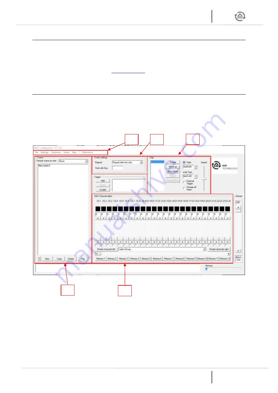
The user interface is clearly divided into 5 areas. 


1.


Administration of scenes 

2.


Scene settings 

3.


Administration of steps 

4.


DMX channel settings 

5.


Menu bar for settings 


Figure 17: DMX-Configurator – user interface 


Different functions for the configuration of the software and hardware can be accessed via the menu 

bar. These functions are separately specified below. 


Summary of Contents for DUODMX Series

Page 1: ...BAB TECHNOLOGIE GmbH DUODMX GATEWAY Documentation Item no 12041 w 12011 w 12111 w 12021 12121 12031 und 12521 Manual version VIII As of 02 2019 Date 19 July 2019 15 58 04 EN...

Page 2: ...e of contents DUODMX GATEWAY 2 BAB TECHNOLOGIE GmbH DUODMX GATEWAY BAB TECHNOLOGIE GmbH H rder Burgstrasse 18 44263 Dortmund info bab tec de Tel 49 0 231 476 425 30 Fax 49 0 231 476 425 59 www bab tec...

Page 3: ...nes 25 5 4 5 Creating steps 26 5 4 6 Colour picker 27 5 4 7 DMX groups 29 5 4 8 DMX master group 30 5 4 9 Behaviour of scenes 30 5 4 10 Saving and loading projects 31 5 4 11 Exporting and importing sc...

Page 4: ...ation 55 5 5 7 Transmitting the configuration data 58 5 5 7 1 Transmitting via network 58 5 5 7 2 Transmitting via SD card 59 6 DUO DMX APP 60 6 1 Configuration of lamps 60 6 2 Configuration of the sc...

Page 5: ...1 Device selection KNX BMX 35 Figure 32 KNX BMX configuration 35 Figure 33 Group address administration 36 Figure 34 Creating group addresses 37 Figure 35 Importing an ESF file 38 Figure 36 Connecting...

Page 6: ...Control of scenes 66 Figure 66 Control of lamps 66 Figure 67 Lamp 1 channel only dimming 67 Figure 68 RGB W lamp 3 4 channel 67 Figure 69 Adding Moods 68 Figure 70 Selecting colours 68 Figure 71 Crea...

Page 7: ...ogram complex sequences The DUODMX GATEWAY is highly suitable for subsequent installation as a device installed in the ceiling A corresponding adapter is available for top DIN rail installation In add...

Page 8: ...face IP SR WLAN device variant item no 12111w It is similar to the IP SR variant The DUODMX GATEWAY is connected with the network via WLAN instead of LAN KNX device variant item no 12021 As KNX twiste...

Page 9: ...ter is mounted to the housing with two screws included in the scope of supply Make sure that the adapter is screwed to the housing through the two grooved holes only These two holes are marked by the...

Page 10: ...e configured as DMX master sending or as DMX slave receiving on demand The device is connected via a 6 pin pluggable screw terminal polarity is indicated on the housing It is also possible to use just...

Page 11: ...and the DMX bus cable can be connected conveniently the screw type plug in terminals see connection diagram below are removable At first connect the cables of the power supply as well as the DMX bus c...

Page 12: ...wo 3 pin pluggable screw terminal polarity is indicated on the housing It is also possible to use just one DMX output The connections are short circuit proof for device type SR Figure 5 DUODMX GATEWAY...

Page 13: ...red with an SD card SD cards in NTFS format are not supported In case that DUODMX cannot be found you must deactivate all network interfaces except for the currently used network interface Please take...

Page 14: ...stem ID 0 cannot be changed In addition to the firmware there is also a DMX Configurator sample project in the installation registry of the DMX Configurator software If necessary it can be used to ove...

Page 15: ...IP WLAN item no 10211w e WLAN master slave is for the following device type o IP SR WLAN item no 12111w Depending on your selection various configuration windows are provided For a detailed descriptio...

Page 16: ...the IP address of the DUODMX GATEWAY or not If adjustment is necessary make the required settings in the fields provided for this purpose IP address subnet gateway Do not change the Multicast address...

Page 17: ...e DUODMX GATEWAY during operation The status LED of the device will go out for a short while for reading the data As soon as the green status LED is on again the configuration is loaded Please note On...

Page 18: ...of the DMX preview The firmware version is displayed together with the IP address and the device name Figure 13 Display of the firmware version If your device does not have the most current firmware...

Page 19: ...switch to a save operating status e g lamp off Once the power supply has been restored all DMX channels are switched to the value 0 Behaviour in case of bus voltage failure only KNX TP device If the b...

Page 20: ...the commands of the bus system would be overwritten by the activated preview So make sure to use either the preview or the appropriate control system KNX TP KNXnet IP EnOcean There are two preview va...

Page 21: ...yed with IP address default setting is the MAC address and device name To activate the preview for only one of the devices on the list the desired device must be marked blue background and then the pr...

Page 22: ...er if it is not switched on at 0 or switched off at 100 Example If the current dimming value is switched off at 50 the dimming process is already completed after 2 6 seconds The function is activated...

Page 23: ...Configurator directly on the DMX end devices The software is suited for any common Windows systems It is provided on the supplied CD or at www bab tec de Service Downloads 5 4 1 USER INTERFACE The use...

Page 24: ...Configurator must be restarted Figure 18 Changing the language 5 4 3 GENERAL DATA STRUCTURE The light images are entered in two different steps The first step is to create a scene which forms a group...

Page 25: ...cenes Note At the beginning of each scene the DMX Configurator assumes that the corresponding DMX channel values have the value 0 Therefore it might be that a scene adds or does not change your DMX va...

Page 26: ...h can then be accessed with a click For each step different DMX values can be set for each channel Dynamic light images can be created by a sequence of several steps with different DMX values The List...

Page 27: ...easy input of RGB colour values The three consecutive DMX channels R G B values are allocated to the selected colour You can access the colour picker by right clicking on the first RGB DMX channel Fig...

Page 28: ...style and on the right you see the colours in a colour circle round style Select the colours as follows Select the colour on the colour illustration Select the brightness of the colour Click on OK to...

Page 29: ...to the group name The DMX channels must be separated by a semicolon It is possible that one DMX channel is allocated to different groups After having defined the groups they are available in the grou...

Page 30: ...e 50 Master 50 equals 25 in the output NOTE This element is only effective for the reproduction preview of scenes with enabled preview function 5 4 9 BEHAVIOUR OF SCENES Scene settings The actions whi...

Page 31: ...if you need the same scene in another project Use the menu item Scene Export to save individual scenes The saved file has the extension scn Use the menu item Scene Import to add an exported scene to...

Page 32: ...irst channel of the desired DMX device e g channel 1 Ch1 Enter the desired name of your DMX device in the Name field of the right hand configuration window e g RGB lamp 1 Now right click on the channe...

Page 33: ...icated project is loaded Select the project file with the field blue arrow Load last file The previously opened project is loaded 5 4 15 MEMORY LEVEL DISPLAY As of DMX Configurator version 1 6 0 0 the...

Page 34: ...nt Select the corresponding bus type for your device variant Overview of bus types device variants The marking on the front side shows which device variant you have KNX BMX is for the following device...

Page 35: ...e network DUODMX GATEWAY KNX Controlled via the KNX twisted pair bus two wire bus In any case the device is controlled via KNX group addresses but the transmission channel of the telegrams is differen...

Page 36: ...rator or 2 Using the ESF data import CREATING GROUP ADDRESSES IN THE DMX CONFIGURATOR If there is no suitable ESF file with appropriate group addresses the required group addresses can be created righ...

Page 37: ...entry you must mark it and press the delete button Del on your keyboard USING THE ESF DATA IMPORT To connect the group addresses of an ESF file group address file with the extension esf it must be ex...

Page 38: ...igurator proceed as follows 1 Importing an ESF group address file Open the menu Extensions KNX Import ESF in the DMX Configurator Figure 35 Importing an ESF file After having selected the desired ESF...

Page 39: ...alue 0 1 Scenes are started by telegrams with the value 1 and stopped or interrupted by the telegram value 0 see chapter LAN KNX To create a connection please proceed as described below Simply drag th...

Page 40: ...up address is illustrated below the object see figure below Figure 37 Connection of the dimmer channels If a DMX channel is switched on via 1 bit the 1 byte communication object adopts the previously...

Page 41: ...ress the following data types must be used 3 byte DPT 232 600 RGB value red 0 255 green 0 255 blue 0 255 4 byte DPT 12 001 4 byte unsigned as RGBW value 0 4 294 967 295 1st byte red 2nd byte green 3rd...

Page 42: ...n assigned a name its MAC address is indicated With a mouse click you can mark a device for the configuration data upload or the activation of the unicast preview 4 Press the Search button to show all...

Page 43: ...case of Pause the ongoing scene is stopped and continues at this point once it has been triggered again In case of Stop the scene starts from the beginning once it has been triggered again 7 Assign a...

Page 44: ...nication sending receiving via the KNX twisted pair two wire bus In any case the device communicates via KNX group addresses but the transmission channel of the KNX telegrams is different The configur...

Page 45: ...he DMX via the SLAVE DMX interface and forwarded to KNX See the following example The configuration shows how a KNX actuator is controlled via a DMX mixing desk The DMX mixing desk is connected to the...

Page 46: ...de must be provided with an appropriate feedback signal group address In this context only the following communication objects of the dimmer channels are relevant Dimmer Out 1 and Dimmer Out 2 1 bit D...

Page 47: ...Y DUODMX GATEWAY BAB TECHNOLOGIE GmbH 47 For a better understanding the previous figure shows the assigned KNX group addresses for the control of the DMX channels in Dimmer Out 1 Dimmer Out 1 configur...

Page 48: ...figuration for KNX IP 5 5 3 3 GROUP ADDRESS CONNECTION See chapter Configuration for KNX IP Connecting the scenes Scene out See chapter Configuration for KNX IP Connecting the DMX channels dimmer out...

Page 49: ...is controlled by EnOcean radio profiles Figure 43 EnOcean device selection 5 5 4 1 CONNECTION OF ENOCEAN PROFILES The left half of the Transmitter column shows all EnOcean profiles received by the DUO...

Page 50: ...or scenes by drag drop Figure 45 EnOcean connection of scenes CONNECTION OF SCENES In case of EnOcean the scenes are started and stopped with the same profile This means that a rocker switch can start...

Page 51: ...e ON side This received EnOcean profile is immediately displayed on the left side of the window NOTE the simple EnOcean button sends a unique EnOcean profile for both sides of the rocker switch See th...

Page 52: ...cean signals thus increasing the signal range There are two options Figure 47 EnOcean repeater function 1 Check boxes for the activation of the EnOcean repeater function EnOcean repeater The device re...

Page 53: ...election The selection applies to the following device types 12041w DUODMX GATEWAY Standalone WLAN 12011w DUODMX GATEWAY IP WLAN 12111w DUODMX GATEWAY IP SR WLAN Figure 48 Device selection WLAN To con...

Page 54: ...iant The DUODMX GATEWAY LED shows whether the remote access to the WLAN network was successful GREEN LED flashes The DUODMX GATEWAY accesses the WLAN network or tries to access it GREEN LED is on The...

Page 55: ...b The figure below shows the configuration for the KNX BMX as an example Press the Search button below the DMX Gateways field All DUODMX GATEWAYs in the network are displayed irrespective of the IP ad...

Page 56: ...in the DMX Configurator and change the IP address settings according to your requirements Figure 52 DMX Configurator IP address settings If you want assign a name to your device Search again for the...

Page 57: ...Save as Please use this project file for the further project setup Figure 54 DMX Configurator saving the project Note If you want to use a new or different project please mind the IP address settings...

Page 58: ...cean switch to the LAN EnOcean tab and if you have selected WLAN switch to the WLAN tab The figure below shows the configuration for the KNX BMX as an example Press the Search button below the DMX Gat...

Page 59: ...In this context the configuration file must always have the same name config par so that it can be identified and imported by the DUODMX GATEWAY The green Power LED indicates the loading status as lon...

Page 60: ...amps it is necessary to know which DMX channels are assigned to a DMX lamp The lamps are defined in the DMX Configurator under Settings device management The procedure is the same as the procedure alr...

Page 61: ...y See Figure 59 Manual IP address Input Approach AUTOMATIC Start Gateway search The DUODMX GATEWAY also has a Discovery function It is used for automatically searching for DUODMX GATEWAYs See Figure 5...

Page 62: ...DUO DMX APP DUODMX GATEWAY 62 BAB TECHNOLOGIE GmbH DUODMX GATEWAY Figure 59 Manual IP address Input...

Page 63: ...annel lamps are dimmed RGB lamps or RGBW lamps are controlled by a colour circle colour picker It is also possible to directly pick colours via four fields See page 67 Moods Under this point Moods are...

Page 64: ...DUO DMX APP DUODMX GATEWAY 64 BAB TECHNOLOGIE GmbH DUODMX GATEWAY Figure 62 About the DUO DMX APP...

Page 65: ...d by the user once in the APP If an entry which has not yet been assigned to a DMX output is selected for the first time under the menu item Lamps or Scene the selection menu pops up in which the DMX...

Page 66: ...O DMX APP Start page Control of lamps and Control of scenes The figures on this page show the available lamps figure to the right and scenes figure to the left of a project example The scenes are star...

Page 67: ...le Figure 68 RGB W lamp 3 4 channel 2 Screen for the control of an individual channel dimming with a slider Figure 67 Lamp 1 channel NOTE In case that one of the favourite colours has to be changed th...

Page 68: ...e accessed via the Moods entry Figure 60 DUO DMX APP Start page see green arrow 6 3 5 1 ADDING MOOD AND SELECTING COLOURS To select a picture for a new Mood press to open the selection dialogue see Fi...

Page 69: ...n directly define the desired colours i e create a sequence without a picture With this symbol the selected picture is faded out and a colour circle is displayed Press the icon to return to the pictur...

Page 70: ...5 2 OPERATING MOODS Click on the Moods to select them on the Moods Screen see left figure A submenu opens up where the Moods can be changed or deleted Press the symbol to open the Moods control right...

Page 71: ...hown The selected colour is now directly reproduced on this lamp Press the Play symbol to start the sequence and reproduce the colours of the Mood one after the other right figure Note The following a...

Page 72: ...in screw terminal Once the switch has been closed or opened the DUODMX GATEWAY triggers the light scene with the corresponding name The names of the light scenes are provided as follows and assigned...

Page 73: ...AB TECHNOLOGIE GmbH 73 8 DMX PLUG SOCKET PIN ASSIGNMENT 3 pol XLR Plug Front view 1 Ground Screen 2 DMX 3 DMX 3 pol XLR Socket Front view 1 Ground Screen 2 DMX 3 DMX DUO DMX Gatway Front view 1 Ground...

Page 74: ...emain save 10 CREATING ESF DATA To create the desired ESF data for the connection in the DMX Configurator you have different options Creating ESF data from the EIBPORT As of the firmware version 1 0 2...

Page 75: ...our knowledge However mistakes cannot be completely ruled out Therefore we need to point out that we neither can give a guarantee nor assume the legal responsibility or any liability for consequences...

Reviews: