AWH TANKO MX125 Operating & Installation Instructions Manual Download Page 77

Jet Cleaner TANKO-MX 


7 Maintenance 

Operating/Installation Instructions 2019/08 

69/102


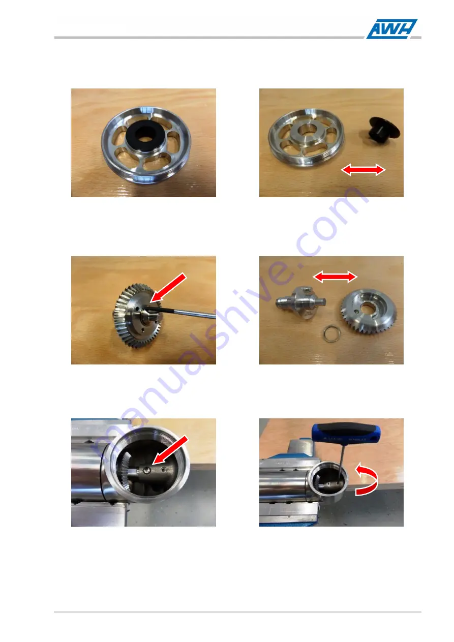
10.  Slide the bearing plate (28) with the collar bushing (08) from the driver shaft (25).  

11.  Push the collar bushing (08) out of the bearing plate (28) with an auxiliary tool (e.g. drift).  

12.  Lever the spiral circlip (31) out of the internal groove on the driver shaft (25), by inserting the flat tip 

of a small screwdriver on the removal notch, and screw it out in a spiral pattern.  

13.  Pull the bevel gear wheel for the nozzle carrier (26) from the driver shaft (25).  

14.  The cylindrical pin (35) is pressed into the driver shaft (25) and should not be removed.  

15.  Pull the bushing (09) from the shaft-axle connection (24) with a set of pliers or lever it out with the 

flat tip of a small screwdriver.  

16.  Unfasten the set screw (34) on the drift of the shaft-axle connection (24) with a hexagon socket 

wrench size 2.5 mm and unscrew it.  

17.  Hold the device firmly with one hand and unfasten the vise.  

18.  Fasten the device vertically in the lower area of the shaft-axle connection (24) so that the 

connection cover (01) faces upwards and the thread for the bearing plate (28) of the shaft-axle 
connection (24) faces to the side.  

Summary of Contents for TANKO MX125

Page 1: ...UCTIONS Translation Container cleaning device TANKO MX125 150 jet cleaner Armaturenwerk H tensleben GmbH Schulstr 5 6 D 39393 H tensleben Germany Telephone 49 39405 92 0 Fax 49 39405 92 111 E mail inf...

Page 2: ...ry in which the partly completed machinery will be assembled or to his authorized representative If any discrepancies arise in the translated text the original operating instructions German must be co...

Page 3: ...ment Parts and Accessories 10 2 3 Duties of the Operating Company 11 2 4 Requirements for Personnel 13 2 4 1 Personal Protective Equipment 14 2 5 Labeling 15 2 5 1 Type Designation 15 2 5 2 Type Plate...

Page 4: ...Removal 56 7 3 1 Removing the Device 57 7 4 Maintenance 59 7 4 1 Maintenance Intervals 60 7 4 2 Tools and Tightening Torque Values 63 7 4 3 Disassembling the Device 66 7 4 4 Assembling the Device 75...

Page 5: ...the device MX150 G12 38 Picture 5 2 7 Threaded connection Example MX125 41 Picture 5 2 8 Nozzle carrier can be rotated 180 42 Picture 7 3 1 Nozzle carrier can be rotated 180 58 Picture 7 4 1 Maintenan...

Page 6: ...industry or biofuel plants DIN Deutsches Institut f r Normung e V is a national standards organization in the Federal Republic of Germany The standards of this organization are referred to as DIN stan...

Page 7: ...system of units for physical variables SN Serial number SW Width across flats wrench size TRBS Technische Regeln f r Betriebssicherheit German technical rules for operational reliability and safety t...

Page 8: ...grees Fahrenheit h Unit of measure for time t hour kg Unit of measure for mass m kilograms Conversion 1 kg 2 20462 lb Latin libra pound l min Unit of measure for volume flow rate V liters per minute C...

Page 9: ...g regulations in regard of the prevention of accidents and in regard of environmental protection in the country of use must also be observed The instructions must be kept at the location of use of the...

Page 10: ...h a medium level of risk Failure to observe it can lead to death or severe physical injury Measure s to prevent the danger CAUTION This warning warns of a hazard with a low level of risk Failure to ob...

Page 11: ...on of the danger 1 Texts which follow this numbering describe the first step of a task followed by further numbered steps which have to be performed in the specified order a Texts which follow this le...

Page 12: ...ical voltage Warning about explosive atmosphere Warning about hand injuries Warning about a hot surface Warning about corrosive substances Warning about substances which are a water hazard Unauthorize...

Page 13: ...operating authorization use of spare parts that do not comply with the specified technical requirements Improperly performed repairs disasters the effects of foreign objects and force majeure Disclai...

Page 14: ...ns described in these instructions must be adhered to WARNING Failure to comply with this manual incorrectly performed installation and repair work or incorrect operation could lead to malfunctions on...

Page 15: ...osive atmosphere Use of the device in an Ex area potentially explosive atmosphere is PROHIBITED There is a risk of death or severe physical injury Follow the information on the type plate of the devic...

Page 16: ...zardous substances This also applies to hazardous substances that may arise during work processes Refer to the order confirmation parts list from AWH for the materials used in the device The TANKO MX...

Page 17: ...ts which are compatible with the materials of the device see Section 3 4 Cleaning media The preferred installation position for the device is vertical with the cleaning head pointing downwards Other i...

Page 18: ...esult in failure of components or a device malfunction as well as material damage and consequential damage There is a risk of death or severe physical injury Use only the manufacturer s original spare...

Page 19: ...his must then be implemented in the form of operating instructions for the operation of the device When using hazardous materials protective measures must be specified in accordance with the safety da...

Page 20: ...nd safety devices required for setting up inspection shutting down including emergency shutdown operation maintenance cleaning and repair The operating company must design the disconnection of the ene...

Page 21: ...ustrial mechanic or similar training practical experience in the assembly disassembly of devices The person must be familiar with the construction mechanical installation maintenance of the device and...

Page 22: ...gloves Wear protective gloves to protect your hands against friction grazes getting pricked or deep cuts and for protection against coming into contact with hot surfaces or chemical substances Protect...

Page 23: ...only apply to devices with types indicated on the title page of these instructions The marking is applied to the device according to the following illustration 1 Device type plate In case of inquirie...

Page 24: ...United States Design No US D790 661 S India Design No IN 281376 China Design No CN 303855808 S 3 1 Structure The TANKO MX series devices are essentially identical in construction The design is primari...

Page 25: ...media connection through a flow in disk and into the device and drives the impeller which is solidly connected to a rotor shaft The cleaning head is connected to the actuator unit in such a way that...

Page 26: ...ufficient earthing and made of conductive material may be cleaned The container outlet must be open during a cleaning process i e no accumulation of cleaning medium should occur When the device is not...

Page 27: ...r for the nozzle carrier 26 is bearing mounted on the driver shaft for the nozzle carrier 25 and connected to the driver shaft by a pin 35 The nozzle carrier 27 is screwed fixedly to the driver shaft...

Page 28: ...psig Operating temperature Cleaning medium 5 C 41 F to 95 C 203 F Ambient temperature Inside the container 5 C 41 F to 95 C 203 F Cleaning time See Section 3 2 1 See Section 3 2 1 See Section 3 2 1 Re...

Page 29: ...ue of LEX 8h 85 dB A Miscellaneous Materials in contact with media other 1 4404 08 AISI 316L C PTFE PEEK PTFE 1 4401 AISI 316 1 4404 08 AISI 316L C PTFE PEEK PTFE 1 4401 AISI 316 1 4404 08 AISI 316L C...

Page 30: ...MX150 G14 1 x 4 nozzles 7 0 mm TANKO MX150 G14 1 x 4 nozzles 8 0 mm Picture 3 3 2 Chart MX150 G14 flow MX150 G12 Variants 3 8 bar 43 5 116 psig TANKO MX150 G12 1 x 2 nozzles 7 0 mm TANKO MX150 G12 1...

Page 31: ...aning media their use and handling For this reason AWH can provide the owner with a few reference points and notes for a device in a container but only as a precautionary measure which must be observe...

Page 32: ...sulfuric acid with acid content 65 aliphatic aromatic and chlorinated hydrocarbons phenols fluorine compounds Cleaning media containing solids or liquids with solid particles or solid content e g abr...

Page 33: ...asing operating time corrosion reactions are possible including where stainless steel is used The appearance of corrosion on supposedly rust proof steels occurs in various classes or types and depends...

Page 34: ...aning device Operating and installation instructions Technical documents in accordance with the order e g certificates and reports The scope of delivery ends at the interfaces of the device see Sectio...

Page 35: ...disposal Packaging materials are valuable raw materials and can often be re used or usefully processed and recycled Improper disposal can cause environmental damage Dispose of packaging materials in...

Page 36: ...conditions Store the device in the original packaging wherever possible Store the device in a clean and dry place e g enclosed dust free room Store the device in stable environmental conditions Preve...

Page 37: ...han 15 min as there is otherwise a risk of shock or even death Wear protective work clothing safety shoes protective gloves and a hard hat for work at heights CAUTION Risk of accidents as a result of...

Page 38: ...illumination level of 300 lx Lux is recommended maintenance value Connection to the Power Supply Connection to the power supply should only be done once the device is securely mechanically attached to...

Page 39: ...particles from the previous production process during cleaning Waste may contain various harmful substances and may NOT be disposed of in ground water in water courses or in the sewage system Improper...

Page 40: ...ce to thump whip Install the device free of mechanical strain Refer to Table 3 3 1 Operating parameters of the device or the pictures in Section 5 2 1 Interfaces for the installation dimensions CAUTIO...

Page 41: ...8 33 102 5 2 1 Interfaces 5 2 1 1 MX125 Installation Dimensions and Interfaces Top view min of the installation opening Front view Top view Picture 5 2 1 Installation dimensions of the MX125 device 63...

Page 42: ...ction MC connection of the downpipe DP to the device B Device Container Process connection PC connection of the downpipe DP to the container C Space for Movement Installation Space Cleaning head with...

Page 43: ...08 35 102 5 2 1 2 Installation Dimensions and Interfaces of the MX150 G14 Top view min of the installation opening Front view Top view Picture 5 2 3 Installations dimensions of the device MX150 G14 63...

Page 44: ...ion MC connection of the downpipe DP to the device B Device Container Process connection PC connection of the downpipe DP to the container C Space for Movement Installation Space Cleaning head with no...

Page 45: ...08 37 102 5 2 1 3 Installation Dimensions and Interfaces of the MX150 G12 Top view min of the installation opening Front view Top view Picture 5 2 5 Installation Dimensions of the device MX150 G12 63...

Page 46: ...ion MC connection of the downpipe DP to the device B Device Container Process connection PC connection of the downpipe DP to the container C Space for Movement Installation Space Cleaning head with no...

Page 47: ...rious faults e g poor cleaning results or impermissible operating states can occur Maintain a minimum distance between the devices depending on their maximum cleaning power This also applies to simult...

Page 48: ...e must be nobody beneath the device when installing removing it NOTE Risk of dirt and foreign objects in the device Functional safety and reliability may be compromised During installation make sure a...

Page 49: ...Example MX125 Picture 5 2 7 Threaded connection Example MX125 1 Remove the screw cap sealing plug from the media connection MC 2 Hold the device firmly with your hands against the cylindrical housing...

Page 50: ...he cleaning jet does not cause vibrations in the surrounding components does NOT influence the rotary movement of the cleaning head due to recoil and does not provoke vibrations in the device itself s...

Page 51: ...ional monitoring equipment on the container to prevent collisions between the mobile device downpipe with cleaning head and any internal fittings The following functions and associated monitoring must...

Page 52: ...performed until the following has been checked Correct mechanical installation of the device on in the container Correct hydraulic connection The safe and reliable functioning of the device the setup...

Page 53: ...hazard assessments CAUTION Risk of hearing damage as a result of an increased noise level The device emits a noise pressure level of LpA 70 dB A When the device is operated in a container the noise le...

Page 54: ...rson may be struck by the jets from the cleaning head There is a risk of death or severe physical injury Do NOT start the cleaning process while there are persons in the container Functional testing 1...

Page 55: ...f death or severe physical injury When commissioning the device the switch on procedure working steps must be followed in the given order SWITCH ON PROCEDURE Work steps 1 Securely close all of the ope...

Page 56: ...otes a pressure surge in a fluid line which is generated by opening closing a shut off fitting e g valve or ball cock quickly at the end of a pipeline Pressure hammers pressure surges can also be prov...

Page 57: ...d from the supply line and device There may also be hot vapors in the container There is a risk of death or severe physical injury DO NOT open the container during the cleaning process Before starting...

Page 58: ...leaning head There is a risk of death or severe physical injury Do NOT start the cleaning process while there are persons in the container NEVER direct the cleaning jet or torrent at persons WARNING I...

Page 59: ...1 Maintenance Intervals During normal operation of the device you must make sure that the mixture of supplied cleaning medium and dislodged substances can flow freely from the container NOTE Clogging...

Page 60: ...or severe physical injury Allow only qualified electricians to perform work on the electrical system Before starting work observe the working steps of the switch off procedure see Section 7 2 Switch o...

Page 61: ...esidual fluid from the supply line and device There may also be hot vapors in the container There is a risk of death or severe physical injury DO NOT open the container during the cleaning process Bef...

Page 62: ...vent them from being inadvertently switched back on or set in motion Do not remove the device unless it has been depressurized Wear protective gloves CAUTION Insufficient lighting in the working envir...

Page 63: ...ose the shut off valve or ball cock Check that the supply of cleaning medium is stopped e g flow meter and there is not media pressure on the device 2 Safeguard the supply of cleaning medium to preven...

Page 64: ...may have protruding sharp edges which can be dangerous when handling it There is a risk of minor cuts Wear protective gloves when working on the device When handling e g unpacking transportation with...

Page 65: ...e device may strike personnel when falling There is a risk of severe physical injury Hold the device firmly when installing removing it There must be nobody beneath the device when installing removing...

Page 66: ...n opening is too small Interface C Picture 7 3 1 Nozzle carrier can be rotated 180 NOTE Excessively small installation opening for the container or components e g agitators in the container Nozzles co...

Page 67: ...aning head device from the downpipe DP inside the container Provided that proper installation and assembly removal of the cleaning head device inside the container is assured 7 4 Maintenance To ensure...

Page 68: ...s are reached Maintenance Intervals and Methods Shorten the maintenance intervals by 30 in the event of Deviation from the preferred installation position of the device see Section 5 2 2 Installation...

Page 69: ...pur gear HR H Plain bearings Spur gear HR bevel gear wheel for housing I Connection Housing bevel gear wheel for housing J Plain bearings Housing shaft axle connection K Connection Shaft axle connect...

Page 70: ...ake sure they are fully functional and for wear Clean or replace the collar bushings as necessary 200 hB V F C H Check the plain bearings to make sure they are fully functional and for wear Clean or r...

Page 71: ...s which are required for performing the required work and approved for use The following tools are required for mechanical work on the device Screwdriver set slot head Hexagon socket wrench size 2 5 x...

Page 72: ...MX150 Special Tool Mounting bell for nozzle carrier MX 1 2 for loosening and attaching the nozzle carrier Art no 664 MWM A44 4A2 0 This mounting bell means that the nozzle carrier 27 can be comfortab...

Page 73: ...the device in the vise are recommended The rinsing ring 07 1 can be positioned freely within the prisms and is thus NOT crushed It is also possible to attach the device in the vise with the mounting a...

Page 74: ...OT grasped without play and in a protective manner by the flats during assembly disassembly then they are at risk of damage For gentle protective assembly disassembly work use an adjustable or pliers...

Page 75: ...elf cleaning with an open end wrench or pliers wrench and unscrew with the jet concentrator 13 3 NOTE The set screw 34 may fall into the device when being unscrewed Insert a hexagon socket wrench size...

Page 76: ...ternal groove on the shaft axle connection 24 by inserting the flat tip of a small screwdriver on the removal notch and screw it out in a spiral pattern 8 Unfasten the bearing plate 28 with an adjusta...

Page 77: ...the nozzle carrier 26 from the driver shaft 25 14 The cylindrical pin 35 is pressed into the driver shaft 25 and should not be removed 15 Pull the bushing 09 from the shaft axle connection 24 with a s...

Page 78: ...s WAF 14 of the shaft of the spur gear 22 Unscrew the actuator unit assembly from the dome of the shaft axle connection 24 20 Remove the collar bushing 07 and the rinsing ring 07 1 from the shaft axle...

Page 79: ...he nozzle carrier 27 Clamp the nozzle extension 12 1 with the nozzle 12 in the vise Unfasten the nozzle 12 and unscrew it from the nozzle extension 12 1 Remove the nozzle extension 12 1 from the vise...

Page 80: ...in the vise in a horizontal position on the housing 02 so that the threaded connection for the bevel gear wheel for the housing 23 is NOT clamped 2 Lever the spiral circlip 30 out of the internal groo...

Page 81: ...spiral circlip 32 and collar bushing 03 and 04 from the housing 02 10 Push the collar bushing 03 out of the planetary carrier 16 with an auxiliary tool e g drift 11 Lever the spiral circlip 32 out of...

Page 82: ...ly The threaded connection cannot be screwed and may become damaged The jaws of the vise must not clamp too firmly and not directly in the area of the threaded connection Hold the housing 02 firmly wi...

Page 83: ...is NOT performed properly can cause damage to the device which puts the functional safety and reliability at risk when re commissioning The failure of components or a device malfunction can cause mat...

Page 84: ...rovided by the lubricant manufacturer NOTE Risk of dirt and foreign bodies in the device Dirt or foreign bodies can compromise the functional safety and reliability of the device During assembly make...

Page 85: ...e screwed and may become damaged The jaws of the vise must not clamp too firmly and not directly in the area of the threaded connection Fasten the housing 02 with the spur gear 21 pressed in in the vi...

Page 86: ...to the collar bushing 06 11 NOTE The spur gears 19 20 have different gearing Two different spur gears type A and type B must always be used Press two collar bushings 04 into each of the spur gears 19...

Page 87: ...irclip 19 with the collar bushing 03 onto the shaft of the spur gear 18 You must be able to rotate the planetary carrier by hand without any noticeable resistance 16 Press the collar bushing 05 into t...

Page 88: ...here is a bore for self cleaning of the device on the face of the nozzle carrier This bore is also used for orientation when disassembly assembly of the device The position of the bore for self cleani...

Page 89: ...as it will go Fasten the nozzle extension 12 1 in the vise Screw the nozzle 12 together with the jet concentrator 13 into the nozzle extension 12 1 and tighten it Remove the nozzle extension 12 1 toge...

Page 90: ...into the dome of the shaft axle connection 24 Tighten the shaft of the spur gear 22 using the flats WAF 14 with an open end wrench 5 Screw the set screw 34 into the dome of the shaft axle connection 2...

Page 91: ...ith the installation opening Depending on the device type please note the following assembly steps Nozzle carrier nozzles NOT freely movable Push the driver shaft 25 into the boring of the bevel gear...

Page 92: ...8 into the bearing plate 28 13 Push the bearing plate 28 together with the collar bushing 08 onto the driver shaft 25 14 Screw the bearing plate 28 into the shaft axle connection 24 and tighten it wit...

Page 93: ...e device from foreign bodies If a threaded pin 34 falls into the device during assembly it must be removed Place the threaded pin 34 on the hexagon socket wrench size 2 5 mm Insert the hexagon socket...

Page 94: ...ed screwdriver The actuator shaft can be rotated but only with noticeable resistance There is an error in the assembly Disassemble the device and correct the error The spur gears of the gear unit prob...

Page 95: ...vice during cleaning The use of incorrect cleaning agent or sharp objects can damage the device The functional safety and reliability of the device may be compromised The cleaning agents must be appro...

Page 96: ...s in an environmentally friendly manner and recycle them 7 5 Spare Parts and Customer Service Spare Parts and Wear Parts Subject to technical modifications in the interest of further development and i...

Page 97: ...ng torque values for screw connections Item Item Item Item Item Item Thread Tightening Torque Nm lbft 01 02 M56 x 1 5 110 120 81 1 88 5 15 33 24 34 27 34 M 5 2 9 3 1 2 1 2 3 02 23 24 28 M54 x 1 0 54 5...

Page 98: ...66MA000100AL0 C PTFE X 10 1 Plain bearing type A 15 0x32 0 24 0 66MA000110AN0 PEEK PTFE X 11 1 Sliding disk 12 0x24 0 1 5 66MA000140AL0 C PTFE X 12 Nozzle see Table 7 5 3 see Table 7 5 4 see Table 7 5...

Page 99: ...ISI 316 33 1 Threaded pin ISO 4029 M5x 6 430159 1 4404 AISI 316L 34 2 Threaded pin ISO 4028 M5x10 430187 1 4404 AISI 316L 35 1 Cylindrical pin ISO 2338 4 x 8 m6 440046 1 4404 AISI 316L Wear parts pack...

Page 100: ...14 8 4 5 66MB000213AL0 4 4 4 4 14 Flow in disk 2 x 45 DB 6 0 G6 66MA02G30S520 1 1 2 x 45 DB 6 0 L6 66MA02L30S520 1 1 27 Nozzle carrier 4 slot type B 66MB040440B20 1 1 1 1 Table 7 5 4 Mx150 G14 Standa...

Page 101: ...afety goggles WARNING Hazardous situations caused by performing work on the device incorrectly There is a risk of death or severe physical injury Repairs and fault clearance work must be performed onl...

Page 102: ...pressure recoil Increase the distance to surrounding components Filter or nozzles blocked Clean the filter or nozzles Effectiveness of cleaning is inadequate Nozzles soiled or blocked Clean or replace...

Page 103: ...th the EMERGENCY STOP in case of emergency is designed to disconnect the entire machine from the supply voltage without delay in order to eradicate the risks caused by electrical voltage immediately S...

Page 104: ...ff procedure see Section 7 2 Switch off Procedure Use protective work clothing protective gloves and safety goggles when carrying out the tasks In case of any uncertainty or doubt contact AWH Removal...

Page 105: ...contact a specialist company to arrange for disposal Comply with locally applicable health safety disposal and environmental protection regulations NOTE Danger due to improper disposal Cleaning agents...

Page 106: ...Words 1 Explanation of the Warnings 2 F Faults 6 93 Faults and Remedial Action 94 Functional testing Trial Run with the Device 46 52 60 G General Function Description 17 I Installation 29 32 Installa...

Page 107: ...and Wear Parts Spare parts 7 10 88 Spare Parts Replacement Parts and Accessories 10 Storage 28 Structure 16 Switch off Procedure 55 Switch on procedure 47 T Technical Data 20 Temperature Ambient tempe...

Page 108: ...Jet Cleaner TANKO MX 100 102 Operating Installation Instructions 2019 08 Appendices Appendices Annex 1 Declaration Translation 101...

Page 109: ...4 1 7 4 1 1 7 4 2 1 7 4 3 The specific technical documents have been compiled in accordance with Directive 2006 42 EC Annex VII Part B The supplied version of the device is consistent with the follow...

Page 110: ...Jet Cleaner TANKO MX 102 102 Operating Installation Instructions 2019 08 Appendices...

Page 111: ...Jet Cleaner TANKO MX A Member of the NEUMO Ehrenberg Group Notes...

Page 112: ...A Member of the NEUMO Ehrenberg Group Armaturenwerk H tensleben GmbH Schulstr 5 6 D 39393 H tensleben Telefon 49 39405 92 0 Telefax 49 39405 92 111 E Mail info awh eu Homepage http www awh eu...

Reviews: