background image

CHAPTER 7: MKIP SYSTEM SHELL

VersAtive

®

Pro Enhanced – Operation Manual 

7-7

7.8  Menu - Eth0 Set Default

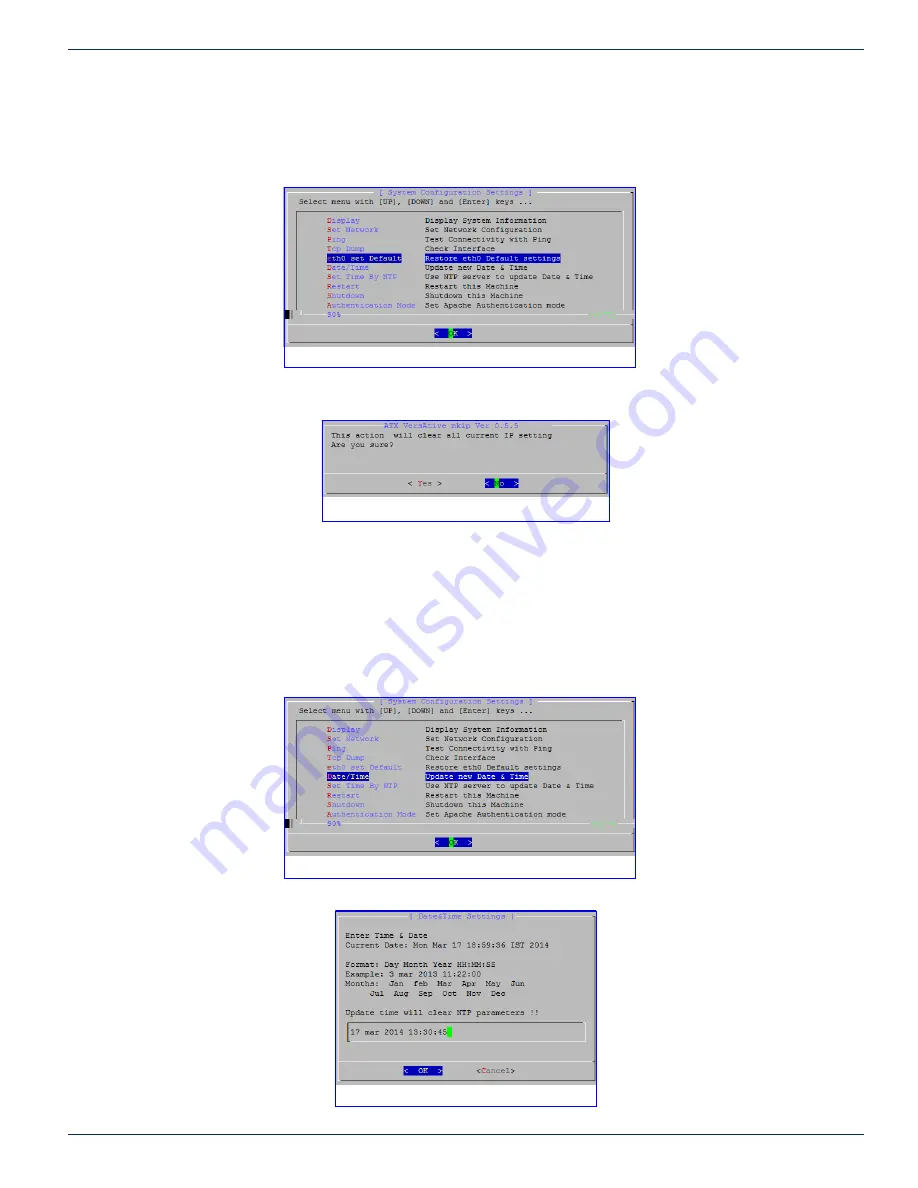
The current settings of the MGMNT management Interface eth0 may be set to factory default 192.168.0.23 with this option.

1. 

Select 

eth0 Set Default

 from the menu, Figure 7-20.

2.  Confirm action, click 

Yes

Figure 7-21.

3.  The change takes place after a reboot. Log in again using 192.168.0.23.

7.9  Menu - Date/Time

The Device time may be set manually from this option. If a date and time is entered, the NTP server IP address, if entered, 

will be removed.

1. 

Select 

Date/Time 

from the menu, Figure 7-22.


Figure 7-20: Select ‘eth0 Set Default’

Figure 7-21: 

Confirm Restore eth0 to Default

Figure 7-22: Select ‘Date/Time’

Figure 7-23: Enter Date/Time in correct format

Summary of Contents for VersAtive Pro

Page 1: ...Operation Manual Patent Pending ...

Page 2: ...ted pages within the document but some may reference outside documents if the reader needs that additional information The Table of Contents is entirely hyperlinked and bookmarks are available but the bookmark feature must be turned on in your Reader application Symbol Usage Throughout the manual some symbols are used to call the readers attention to an important point The following symbols are in...

Page 3: ...r Contents 2 1 2 2 General Tool Bar 2 1 2 3 General Right Click Menu 2 1 2 4 Products Upgrade 2 2 2 5 System Time 2 4 2 6 User Management 2 4 2 7 Licence 2 5 2 8 SNMP 2 6 3 DEVICE CONFIGURATION 3 1 3 1 Chapter Contents 3 1 3 2 Settings and Info 3 1 3 3 Network 3 2 3 4 Licence Information 3 3 3 5 Maintenance 3 4 4 TRANSCODING APPLICATION 4 1 4 1 Chapter Contents 4 1 4 2 Ethernet Resources 4 1 4 3 S...

Page 4: ...SHELL 7 1 7 1 Chapter Contents 7 1 7 2 Connect Using Monitor Keyboard and Mouse 7 1 7 3 MKIP Shell Menu 7 2 7 4 Menu Display 7 2 7 5 Menu Set Network 7 3 7 6 Menu Ping 7 5 7 7 Menu TCP Dump 7 6 7 8 Menu Eth0 Set Default 7 7 7 9 Menu Date Time 7 7 7 10 Menu Restart 7 9 7 11 Menu Shutdown 7 9 7 12 Menu Authentication Mode 7 9 8 SERVICE SUPPORT 8 1 8 1 Contact ATX Networks 8 1 8 2 Warranty Informatio...

Page 5: ...ewing Monitoring Flash Media Server listens for RTMP E requests on port 1935 TCP Clients attempt to connect over ports in the following order 1935 80 RTMP 80 RTMPT 1935 UDP RTMFP Adobe Flash Previewing Monitoring Flash Media Server listens for RTMFP requests on port 1935 UDP 8443 TCP HTTPS HTTPS Communications 1 2 1 Notes on Opening Fire Wall Port 1935 for Monitoring Some firewalls reject traffic ...

Page 6: ... 2 2 Enter the IP address of the Management Port factory default 192 168 0 23 3 Login with credentials case sensitive User Name vms Password VMS 4 The GUI will open as shown in Figure 1 3 1 5 Configuring the Device Quick Summary These are the key steps required to set up the Device 1 5 1 This Chapter GUI Overview Open the GUI and log in 1 5 2 General Configuration Chapter Managing Firmware Managin...

Page 7: ... Start Transcoding from the Resource icon 1 6 The GUI The GUI is based on a familiar Tree and Tabbed Pane design Figure 1 3 The main parts are 1 Tree View of Managed Elements 2 Pane View of the Selected Element 3 Tool Bar 4 Context Sensitive Right Click Menu 5 Tree View Search Tool 6 Details View for Selected Element 7 Alarms Notification Panel 8 Events Notification Panel Managed Elements are disp...

Page 8: ...an Ethernet Resource for receiving content 2 Add Capture Resource Not used on this VersAtive Device 3 Export Resources Saves a backup copy of the resource parameters to a file or series of files Allows selection of any or all of the created resources which include any SPTS streams and their publish points 4 Import Resources Import or restore resources from a file saved earlier 5 Reboot VersAtive R...

Page 9: ...audio and video 6 Preview A powerful feature used to open a low resolution thumbnail picture for viewing the incoming stream Each resource may be enabled for preview individually during setup For more information on this feature see 6 3 Preview or Monitor Resources on page 6 3 7 Copy Paste A feature used along with the Paste feature under the Device to quickly replicate Resources Will copy all str...

Page 10: ...View All pasted objects represent exact images of the copied source and will require some editing to avoid duplication within the Device The process is the same for all Copy Paste operations whether Streams or Publish Points are being copied 1 10 1 Copy Paste Streams 1 Select the Donor Resource with an SPTS Stream and Publish Points that it is desired to replicate Figure 1 6 2 Create a Recipient R...

Page 11: ...copy of the stream is replicated on the new Resource Figure 1 9 WARNING The replicated Streams will have identical properties to the copied Streams so conflicting properties must be edited manually before the Stream may be started A warning is given see Figure 1 10 4 Figure 1 8 Select Paste 5 Figure 1 9 Stream Replicated Figure 1 10 Stream Replication Warning ...

Page 12: ...me 12 Tick the box next to any of the PIDs for audio Teletext and private data which should be active these are unselected by default during the Paste operation 13 Next Tick the box of the Connection to be edited There could be more than one connection to be edited 14 Click Edit to enable changing the IP address and input interface port 15 Next Edit the IP address to the correct value for this pub...

Page 13: ... uploading new firmware Upload Version Uploads new firmware version to upgrade the VersAtive system See 2 4 Products Upgrade on page 2 2 for procedure Shutdown General This gracefully shutdowns the unit When the unit is shutdown the front panel Power button must be pressed locally to power the unit back up again Restart VersAtive Restarts the entire user interface warm re boot of the machine 3 Tab...

Page 14: ...pport group Save the file first to your local PC or accessible drive Procedure This procedure explains how to upload then install new firmware versions to the VersAtive Pro After uploading the firmware will reside on the integral Device hard drive for subsequent installation now or at a later time Uploading saves the firmware to the Device hard drive it does not install the firmware 1 Click on the...

Page 15: ...The firmware upgrade process will begin and a progress screen is presented Figure 2 8 Soon the SEULA Software End User Licence Agreement is presented Figure 2 9 7 Click the I Agree box 8 Click Accept Login to the GUI and check the Device Basic Info page to see that the firmware is installed see 2 4 1 View Current Firmware Version on page 2 2 and Figure 2 3 Figure 2 6 New Uploaded Version 5 6 Figur...

Page 16: ... Internet 1 Click General Icon at top of Tree View Figure 2 10 2 Click the System Time tab 3 Select the Button Set Time from NTP server 4 Enter the IP Address or URL of the desired NTP server 5 Select the appropriate Time Zone from the dropdown menu 6 Click the Apply button 2 6 User Management A single user with Administrator authority is defined by default but users may be added or managed as req...

Page 17: ...relies on installed licenced software and you may view licences if required 2 7 1 General Licence Click the General icon in Tree View to view this page which is for information only and displays the VMS licence installed on the platform Open source licences may be viewed by clicking the link 2 7 2 Device Licence In the Tree View click the Device icon to view the transcoding Device Licences install...

Page 18: ...P manager 4 Click Add IP button to add this IP address to the list 5 Click Save to apply the changes Repeat to add more SNMP Managers 2 8 2 Download and Compile the MIB The MIB will need to be compiled to the SNMP Manager and it is stored locally on the Device hard drive It may be obtained from the link on the SNMP tab Procedure This procedure explains how to access the Device MIBs and extract the...

Page 19: ...Trap This trap appears when the user is updated in the VMS Update can be in the user name password or permissions userLoginTrap This trap appears in two situations When the user logs in to the VMS successfully or unsuccessfully userLogoutTrap This trap appears when the user successfully logs out VersAtive Communication Traps versativeConnectTrap This trap appears when the VersAtive connects succes...

Page 20: ... VersAtive has no connection to publish point or VersAtive cannot publish the stream This trap can be only an Error versativeMonitorResourceStatusTrap This trap appears when there is no input for the resource and the VersAtive retries to connect This trap can be a warning or info Warning indicates the name of the resource and that the VersAtive is retrying Info indicates the name of the resource a...

Page 21: ...detected versativeExternalStopSignalReceivedTrap This trap appears when User initiates stop resource versativeEvntPsiMonitoringTrap This trap appears when there is a PSI change at the input versativeEvntCcErrorTrap This trap appears when the resource has a continuity count error versativeCapcardInputChangedTrap This trap appears when the capture card format changes versativeMcEncValidationErrorTra...

Page 22: ...Analog Card Temp is High VersAtive MPTS MUX and MQAM Traps versativeMuxStartTrap This trap appears when the mux is started This trap can be an error or info Error message indicates that the mux didn t start Info message indicates that the mux started successfully versativeMuxStopTrap This trap appears when the mux is stopped This trap can be an error or info Error message indicates that the mux di...

Page 23: ...e Device configuration is done from the Settings and Info page 3 2 1 Basic Info Page The Basic Info tab shows information about the hardware model and platform in this case VersAtivePro Small as well as the installed version of firmware Figure 3 1 The main information and configurable features are 1 The version of installed firmware 2 The hardware model of the platform 3 The editable Name of the D...

Page 24: ...ddresses 1 Click on the Device icon to select it in Tree View Figure 3 2 2 Click the Settings and Info tab if it isn t already selected 3 Click the Network tab 4 Optionally click the Erase Icon for the eth port to be changed to delete all current settings Alternately you can just edit the current settings 5 After editing settings as required for any eth interface click the Gateway adjacent radio b...

Page 25: ...lick on the Device icon to select it Figure 3 3 2 Select Settings and Info tab if it isn t already selected 3 Select the Network tab 4 Enter the IP Address of the DNS server 5 Click Save 3 4 Licence Information Select the Device in Tree View then the Licence Information tab to view installed VersAtive Device Transcoding licences Licences do not expire and are unlimited in transcoding capabilities ...

Page 26: ...be useful Clean Log Procedure 1 In the Tree View click the Device icon to select it Figure 3 5 2 Click the Maintenance tab 3 Click the Clean Log Files button There is a prompt to delete all the log files choose Yes You may get an error message bug but the log files were deleted Download Log Procedure 1 In the Tree View click the Device icon to select it Figure 3 6 2 Click the Maintenance tab 3 Cli...

Page 27: ...tream 4 2 Ethernet Resources An Ethernet Resource is an input to the platform which exists on one of the Ethernet interfaces as an IP stream These resources are used as source content for subsequent transcoding 4 2 1 View Resource Attributes Existing Ethernet resource attributes may be viewed by clicking the resource in the Tree View 1 Click on the Resource icon in Tree View to select it Figure 4 ...

Page 28: ...t will be later enter the Program Name Program Number select Start On Signal then click Save Offline to save the settings The stream will start when the signal is detected 8 Click Analyze only for streams that exist currently on a physical or virtual input not required for Save Offline NOTE The Save Offline feature makes is possible to set up streams that are not yet present on the input ports but...

Page 29: ...ource 13 The Program is added to the Resource Figure 4 5 and shown in the Tree View under the Device with the included SPTS Incoming stream PIDs detailed in the adjacent Pane View This is automatically saved 14 The Preview ON tick box is selected by default Untick the box to disable Preview for this resource only and click Save if a change was made NOTE The Preview function requires a small amount...

Page 30: ...this greys out all audio settings Default unticked Codec Dropdown menu Choices MPEG1 L2 MP3 AAC AC3 EAC3 HEAAC AC3 Dialnorm Scroll Control Enabled on AC3 and EAC3 signals only Controls playback gain within the Dolby AC3 compression system setting the overall program playback level for loudness normalization The audio level between different TV programs channels and in particular commercials is inc...

Page 31: ...or MPEG2 codec Controls quality of MPEG2 encoding within the set bitrate Settings between relative values 0 and 31 with 16 as default Increase or decrease relative quality CABAC Tick box Enabled on H 264 profiles Enables CABAC Context Adaptive Binary Arithmetic Coder stream compression and reverts to CAVLC Context Adaptive Variable Length Coder system if un ticked which significantly reduces effic...

Page 32: ...hernet Resource icon in the Tree View Figure 4 7 2 Select New SPTS Stream on the Tool Bar 3 On the settings page Figure 4 8 give the stream a meaningful Name such as the service name or accept the default 4 Edit Video Audio Video Pre processing Parameters as required NOTE For details and guidance on configuring these settings see 4 3 SPTS Stream Configuration on page 4 4 5 Click Apply to save and ...

Page 33: ...teger Un tick Automatic to enable entering a CBR bitrate for the Video stream Automatic Tick Box Tick to turn on Variable Bit Rate output Un tick to set to CBR then enter an integer in CBR Out Default is ticked VBR Program No xxxx Integer Enter the MPEG program number to change default value PCR PID xx Integer Default is PCR PID follows Video PID PMT PID xx Integer Program Map table PID Video PID ...

Page 34: ...eam Publish to an existing SPTS Stream 1 Select the SPTS Stream by clicking it Figure 4 10 2 Select New Publish on the Tool Bar 3 Give the Publish point a meaningful Name such as IP Address or type of publish or accept the default Figure 4 11 4 Add a New Connection by adding IP address and port number then choose the physical Output Ethernet Interface and protocol Ports available may differ betwee...

Page 35: ...e adjacent tick box then click Edit or Delete 9 After the Connection is created click Apply or after editing click Save to apply the changes the button changes from Apply to Save once the publish is created Figure 4 13 10 The Publish is added to the SPTS Stream and displayed in Tree View 7 8 Figure 4 12 Connection Created 9 10 Figure 4 13 Publish Added to SPTS Stream ...

Page 36: ...tton on the Tool Bar or the Right Click Menu 3 The Streaming starts and is indicated in the Tree View by small triangles in the lower right corner of all streaming Element Icons Figure 4 15 4 7 1 Streaming Icon Indicators When streaming starts the icon for each element changes to show a small triangle to indicate that Before the streaming is started the icons appear without triangle indicator Figu...

Page 37: ...evice platform either Active Streaming and note the small blue triangle in the icon Figure 5 2 or Idle 4 Enabled Reports on the Device Enabled or Disabled it is possible to disable the device from the right click menu in Tree View 5 2 1 Reviewing Alarms Open the Alarms window by clicking the Alarms Button top right corner of the GUI Figure 5 1 1 The Alarms window opens and displays the current ala...

Page 38: ...nts 2 The sort ordering can be changed by clicking the column header All headers toggle and sort the list between top down bottom down when clicked 3 Click the control actions to clear events or open Events History window 4 Search an alarm condition with criteria The list is dynamically refreshed with the items matching the entered string 5 Review a long list of alarms with the Previous Next actio...

Page 39: ...Apply button initiates the action All filter settings require Apply button to initiate action 4 Events are displayed by default in chronological order most recent first Use scroll bars or mouse wheel to view list extents 5 The sort ordering can be changed by clicking the column header All headers toggle and sort the list between top down bottom down when clicked 6 Search an alarm condition in the ...

Page 40: ...CHAPTER 5 ALARMS EVENTS 5 4 VersAtive Pro Enhanced Operation Manual This page intentionally left blank ...

Page 41: ...e Device The Device may be monitored at a Hardware level which is the underlying machine motherboard 1 In Tree View click the Device icon Figure 6 2 2 Click to select the Device tab 3 CPU Load The histogram of average CPU load over the last 30 seconds displayed in Green 4 RAM The histogram of average RAM usage over the last 40 seconds 5 CPU Heat The histogram of average CPU temperature over the la...

Page 42: ... See History link shown in Figure 6 3 1 In Tree View click the Device Icon 2 Click to select the Device tab 3 Click the See History tab A number of options may be selected to determine the length of history The exact dates may be selected from the calendar by clicking in the From and To windows Figure 6 4 Preset time periods of from the last hour up to last 2 weeks may also be selected 1 2 3 Figur...

Page 43: ...ificed in order to maximize transcoding power In this case a user may disable Preview to lower CPU load 6 3 1 Video Preview Any single Resource may be Previewed to determine the content or quality of the ingested video before the content transcoding is started Video is displayed at 5 frames sec Preview of audio is not supported Adobe Flash is required for the preview function and some browsers or ...

Page 44: ...ane View window 5 The video is soon presented in a window Figure 6 8 6 Stream parameters such as bit rates are displayed in the Pane View 7 The Resource in Tree View shows a purple triangle indicating Preview monitoring is active Figure 6 8 This must be manually stopped before adding SPTS Streams or starting transcoding 8 To stop the Preview Right Click the Monitored Resource to open the menu Figu...

Page 45: ...Device Or Monitor tab 6 4 Displaying Stream Information During monitoring there is full stream information available that is displayed by default but this may be turned off 6 4 1 View Less Stream Information While the Monitoring tab is selected expanded stream information shown in the Pane View window is the default setting Turning off Expanded Information 1 Click the Monitoring tab if it isn t al...

Page 46: ...CHAPTER 6 MONITORING 6 6 VersAtive Pro Enhanced Operation Manual This page intentionally left blank ...

Page 47: ...u Ping Menu TCP Dump Menu Eth0 Set Default Menu Date Time Menu Restart Menu Shutdown Menu Authentication Mode 7 2 Connect Using Monitor Keyboard and Mouse 1 With the Device turned off connect a VGA monitor to the rear panel VGA port 2 Connect a USB keyboard and mouse to any of the Device USB ports 3 Turn on the Device The monitor screen will display messages from the Device boot up application Onc...

Page 48: ...virtual interfaces which may used for VLAN tagging Ping P PING is a network interface utility to test connectivity to other network Devices TCP dump T Allows the user to check source multicasts on each of the eth ports eth0 set Default e Restores all eth0 settings to their Factory Setting with the management IP address eth0 set to 192 168 0 23 Date and Time D Enter date and time manually This disa...

Page 49: ...TE For eth0 settings only the GUI may be used to set eth0 IP parameters MKIP may only be used to set eth0 to default IP address of 192 168 0 23 Setting the Management IP address 1 Select Set Network Figure 7 5 2 Click OK to open the Network Configuration Settings page Figure 7 6 3 The eth0 network is selected click OK to set the eth0 IP Address the Management port or arrow down to select another p...

Page 50: ...enter any IP address 7 If the default gateway IP address was set and this interface default gateway is not already the current machine default gateway you are prompted next to set that Figure 7 10 Select yes to set it as the default or no 8 When finished and you accept the changes Figure 7 11 the server will reboot 9 Reconnect on the new IP address if changed Figure 7 7 Set IP Address Figure 7 8 S...

Page 51: ...gure 7 12 2 Enter a target address on the network Figure 7 13 3 Depending on the ability to reach the destination target address one of the following results will be obtained If target is not reachable Figure 7 14 If target is reachable Figure 7 15 4 Strike any key to return to the menu Figure 7 12 Ping Figure 7 13 Enter Target IP Figure 7 14 Output for no Connectivity Figure 7 15 Output for Conne...

Page 52: ...ct TCP Dump from the menu Figure 7 16 2 Specify a target interface by typing the interface name Figure 7 17 Click OK 3 A time limit for this dump must be specified in seconds Figure 7 18 Click OK 4 Receive the output of the TCP dump on your terminal session screen Figure 7 19 Figure 7 16 Select TCP Dump Figure 7 17 Select an Interface Figure 7 18 Enter a time limit Figure 7 19 View the Dump Data ...

Page 53: ...20 2 Confirm action click Yes Figure 7 21 3 The change takes place after a reboot Log in again using 192 168 0 23 7 9 Menu Date Time The Device time may be set manually from this option If a date and time is entered the NTP server IP address if entered will be removed 1 Select Date Time from the menu Figure 7 22 Figure 7 20 Select eth0 Set Default Figure 7 21 Confirm Restore eth0 to Default Figure...

Page 54: ...r It cannot be set from the GUI 1 Select Set Time By NTP from the menu Figure 7 24 2 Enter the IP address of the NTP server Do not use the url Figure 7 25 Click OK 3 In the open dialog shown in Figure 7 26 note the time zone that is currently set If this time zone is incorrect then after setting the NTP IP address you must also set the Time Zone from the menu next 4 If the time zone was incorrect ...

Page 55: ...om the defined server 7 10 Menu Restart Shutdown and restart the server from this option 7 11 Menu Shutdown Shutdown the server from this option The server will not restart 7 12 Menu Authentication Mode Local Authentication Only GUI authentication with username and password is supported In this mode the User name and the Password are required Both the Apache2 username password and mkip password Fi...

Page 56: ...CHAPTER 7 MKIP SYSTEM SHELL 7 10 VersAtive Pro Enhanced Operation Manual This page intentionally left blank ...

Page 57: ...PORT Tel 905 428 6068 Toll Free 800 565 7488 USA Canada only Press 3 for Technical Support Then press 1 for Digital Video Products DVIS DigiVu UCrypt VersAtivePro DigiStream Email digitalvideosupport atxnetworks com CUSTOMER SERVICE ATX Networks 1 501 Clements Road West Ajax ON L1S 7H4 Canada Tel 905 428 6068 Toll Free 800 565 7488 USA Canada only Press 1 for Customer Service Fax 905 427 1964 Toll...

Page 58: ...n Canada Rev 08 17 ANW1223 1 501 Clements Road West Ajax ON L1S 7H4 Canada Tel 1 905 428 6068 Toll Free 1 800 565 7488 Fax 1 905 427 1964 Toll Free Fax 1 866 427 1964 www atxnetworks com support atxnetworks com ...

Reviews: