


24
Installation: FibreBridge 2400R/D
LED indicators
An LED header provides support for light pipes to
allow LEDs to be run to either side of the
FibreBridge 2400R/D.
Power:
indicates if power is available from the
supply.
FC 1 and FC 2 Activity:
LEDs blink to show
activity on the Fibre Channel ports (numbered 1
and 2). During very high activity, the LEDs
appear to be steadily lit.
SCSI 1 Activity, SCSI 2 Activity:
each SCSI bus
has its own LED to show activity on that bus
(numbered 1 and 2).
Ready:
should light after power has been applied
indicating the FibreBridge is ready to operate.
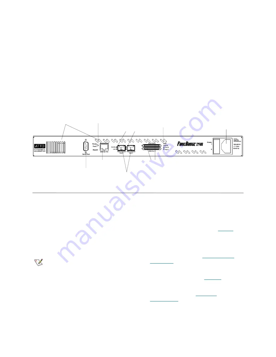
Exhibit 1.8-1 Connectors, LEDs and power receptacle
Installation instructions
1
Physically place the FibreBridge on a desktop
or into a rack.
a.
To mount on a rack, install “L” brackets
so that either the front or the connector
side of the FibreBridge faces front. The
mounting holes on the bracket fit a
standard 19-inch rack using a centered
1.25-inch (31.7 mm) hole pattern.
b.
Install the FibreBridge horizontally
within the rack so it does not reduce the
air flow.
Note
The power requirements of the ATTO
FibreBridge plus the power draw of the other
equipment in the rack must not overload the
supply circuit and/or wiring of the rack.
c.
Properly ground the FibreBridge to the
rack equipment. The earth ground
connection must be maintained.
2
Connect a SCSI device to the FibreBridge.
Connect the Fibre Channel port to your
SAN.Connect the Ethernet cable from the Fibre
Bridge to your computer. Refer to
Cabling
on
page 3.
3
Connect the power connector.
4
Apply power.
5
Access FibreBridge Services using the
QuickNAV utility. Refer to
Configuring the
FibreBridge
on page 64.
6
Go to the ExpressNAV
Restart
page and
restart the FibreBridge.
7
Map your devices.Refer to
Mapping
on page
67.
8
Boot the computers on the SAN and check the
configuration. Refer to
Additional
configurations
on page 17.
Ready/Fault LED
Ethernet port
Fibre Channel ports
SCSI ports
SCSI activity LEDs
FC activity & link LEDs
Serial port
Power receptacle
air vents
Summary of Contents for ATTO FibreBridge 2350C
Page 2: ......
Page 3: ......
Page 11: ......
Page 29: ...18 Installation FibreBridge 2300R D Exhibit 1 5 3 FibreBridge 2300 board layout...
Page 79: ...68 Configuration mapping Exhibit 3 1 1 Mapping using ATTO ExpressNAV...
Page 85: ...74 Configuration mapping...
Page 105: ...xiv Appendix...
Page 109: ...xviii...


