


10
Installation: FibreBridge 1180D
Serial port
The RS-232 serial port provides support for
remote monitoring and management through a
command line interface, menu system or
graphical interface (ATTO Technology
BridgeTools).
LED indicators
FC Activity:
LED blinks to show activity on the
Fibre Channel port (numbered 0). During very
high activity, the LED appears to be steadily lit.
SCSI Activity:
shows activity on the SCSI bus
(numbered 0).
Ready:
should light after power has been applied;
indicates the board has completed the
initialization process without any failures and is
ready to handle data transfer.
Installation instructions
1
Physically place the FibreBridge on a desktop
or mount in a rack. To mount in a rack
a.
Attach “L” brackets so that the front
side with the LEDs faces front and the
connector side is at the back.
b.
Install the FibreBridge horizontally
within the rack so it does not reduce the
air flow within the rack.
c.
Properly ground the FibreBridge to the
rack equipment. The earth ground
connection must be maintained.
The power requirements plus the power
draw of the other equipment in the rack
must not overload the supply circuit and/or
wiring of the rack.
2
Connect a SCSI device to the FibreBridge.
Connect the FibreBridge to your SAN: attach
short wave optical cables or MIA compliant DB-
9 connectors into the Fibre Channel port on the
FibreBridge. Connect to the management
(services) port via the RS-232 serial port. Refer
to
Cabling
on page 3.
3
Connect the power connector.
4
Apply power.
5
Use ATTO BridgeTools, a graphical interface
utility enclosed with your FibreBridge, to
connect to FibreBridge Services. (Refer to
ATTO BridgeTools for FB1180 only
on page
35).
6
Map your devices to the FibreBridge Fibre
Channel port. (Refer to
Mapping
on page 67).
7
Boot the computers on the SAN and, if
necessary, set up the configuration for the
devices connected to the FibreBridge using
ATTO BridgeTools and the information in the
following chapters.
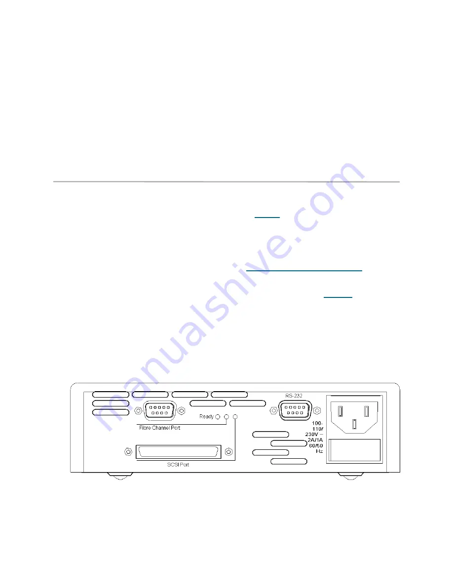
Exhibit 1.2-2 FibreBridge 1180D back panel
Summary of Contents for ATTO FibreBridge 2350C
Page 2: ......
Page 3: ......
Page 11: ......
Page 29: ...18 Installation FibreBridge 2300R D Exhibit 1 5 3 FibreBridge 2300 board layout...
Page 79: ...68 Configuration mapping Exhibit 3 1 1 Mapping using ATTO ExpressNAV...
Page 85: ...74 Configuration mapping...
Page 105: ...xiv Appendix...
Page 109: ...xviii...


