95
ATmega103(L)
0945G–09/01
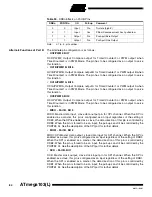
• AC+ – Port E, Bit 2
AC+, Analog Comparator Positive Input. This pin is directly connected to the positive
input of the analog comparator.
• AC- – Port E, Bit 3
AC-, Analog Comparator Negative Input. This pin is directly connected to the negative
input of the analog comparator.
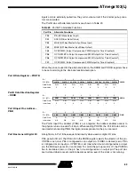
• INT4..INT7 – Port E, Bits 4 - 7
INT4..INT7, External Interrupt sources 4 - 7: The PE4 - PE7 pins can serve as external
interrupt sources to the MCU. Interrupts can be triggered by low level or positive or neg-
ative edge on these pins. The internal pull-up MOS resistors can be activated as
described above. See the interrupt description for further details, and how to enable the
sources.
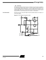
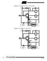
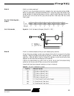
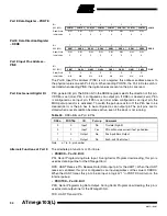
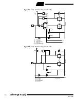
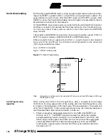
Port E Schematics
Note that all port pins are synchronized. The synchronization latches are, however, not
shown in the figures.
Figure 66.
Port E Schematic Diagram (Pin PE0)

