


73
3.7
Platform operation devices which are not part of the safety
system
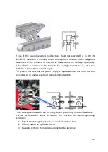
On both connecting rod assemblies (right and left) connecting the tracked
chassis and the central frame, there are two Can Bus angle sensors.
The angle sensors are redundant (thus consisting of two separate sensors) and
monitor the X inclination axis of the respective connecting rod.
The values of the two sensors are constantly compared with the X values of the
sensors attached to the frame.
By measuring their difference, it is possible to determine the relative position of
the connecting rod with respect to the frame.
The position of the two connecting rods is used by the control unit to decide
which one should be moved during the lateral levelling operations (according to
the X axis).
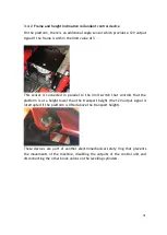
Since neither the travel height nor the operating height depend on the position
of the connecting rods, they are not part of the safety system but only of the
system required for the operation of the machine.
Summary of Contents for 1090 EVO
Page 7: ...7...
Page 22: ...22...
Page 23: ...23...
Page 49: ...49 37 Combustion engine 38 Fuel tank 39 Bi levelling chassis 37 38...
Page 78: ...78...
Page 80: ...80...
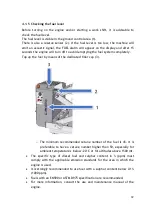
Page 122: ...122 In this configuration the oil level must be as shown in the figure below A 60mm...
Page 144: ...144...
Page 145: ...145...
Page 146: ...146...
Page 147: ...147...
Page 148: ...148...
Page 149: ...149...
Page 150: ...150...
Page 151: ...151...
Page 152: ...152...
Page 161: ...161 8 ATTACHMENTS 8 1 Declaration of conformity...
Page 163: ...163 MANDATORY ROUTINE INSPECTIONS Date Observations Seal Signature...
Page 177: ...177 8 4 Hydraulic diagram See attachment 8 5 Wiring diagram See attachment...