QSG_F670_363.00_EN_01_2021-02-09
38/42
Additional functions
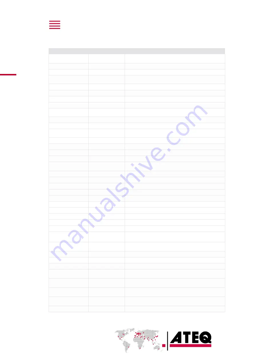
Label
Function
Description
24V OUTPUTS
Auxiliaries output 24
V
Available outputs for external automatism
ABSOLUTE
Absolute
Display the absolute value of the results
ATF
ATF time
Absorb the important leak variations at the defined time
ATR0
/
ATR1
/
ATR2
/
ATR3
ATR 0 - 3
Specific filters on leak measurement
AUTO CONNECT
Automatic connector Function to manage automatic jigs
BUZZER
Buzzer
Buzzer activation configuration
BYPASS
Bypass function
External fast filling valve management
CODE READER
Bar code reader
Bar code configuration
CUT OFF
Cut off
All the measurements that are lower than the configured rate
have the value 0
DISP. OPT.
Display option
Display of an additional information on a second line
DISPLAY MODE
Display Mode
Leak measurement resolution
END OF CYCLE
End of cycle
Several automatism case depending on fail part
management
FILL MODE
Fill types
Special filling methods
FILTER
Filtering
Stabilize the measurement values
FLOW LEVEL
Flow level
Add a minimum fail parameter
INDIRECT
Indirect mode
Specific test mode: test part under bell
MINI-VALVE
Mini valve
Access to highest time resolution (fast test) and auto zero
time
NAME
Name
Program customization
NO NEGATIVE
No Negative
Replace negative value per 0
N TESTS
N tests
Repeats the test when the results get close to the reject level
PEAK HOLD
Peak hold
Give as result, the highest flow during the test time
PR:SEQUENCE
Sequencing
Allowed program automatic sequencing
PRE-FILL
Pre-fill types
Special filling methods
PRESS. CORR.
Pressure correction
Calculate leak measurement at a specific pressure value
PRESSURE DROP
Pressure drop
Pressure drop mode function in the Desensitized mode
REF. VOLUME
Reference volume
Adjust the reference volume value with flow units only
REWORK LIMIT
Rework limits
Additional levels for specific reworkable parts
Sd Part / SD PART 2 /
SD PART 3
Sealed part
Several optional ways to test sealed parts
SEALED DIFF
Sealed differential
Allows testing small parts volume difference between test
and reference volumes
SIGN
Sign
Return opposite result
STAMPING
Stamp
Pneumatic or electric output to identify the part
STD CONDITIONS
Standard conditions
Standard conditions correction with parameters
SYNC. TEST
Synchro test
A programmable input allows to pass from Stabilization to
Test phase
T+R TEST
Test and reference
test
Display which part has failed during a test with two parts
TEMP.CORR. 1
Temperature
correction
Software temperature test part correction
TEMP.CORR. 2
Temperature
correction
Hardware temperature test part correction
TEST CHECK
Calibration check
Calibration check by adding a volume at the end of test time


