background image

SECTION 5 

TROUBLESHOOTING 


73 


Toolbox System Status Messages (

Continued

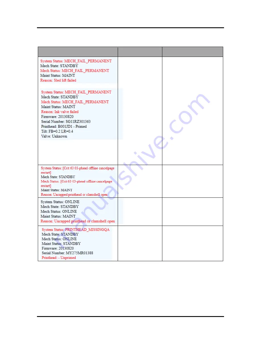
SYSTEM STATUS 

SOURCE 

SOLUTION 


Mechanical error 

One of Printer's 
mechanical 
components was not 
properly registered at 
expected position. 

Mechanical failure or 
Sensor failure. 

Visually inspect component 
stated as a 

“Reason” for failure. 

Using 

Scan Sensors

 page in 

Toolbox

, perform toggle test on 

Sensor responsible for 
registration of failed mechanical 
component position. 

Lifter Arm Sensor is dirty or 
damaged, Lifter Motor Cable is 
unplugged, operator's side 
Lifting Arm is damaged, or 
Lifting Arm mechanism is stuck.  

Dual Pinch Valve problem:


Check Sensor board connector 
and flag/sensors alignment. 
Check Valve motor connector. 
Check P2005 cable on MPCA. 

At this point, this error may 
represent an Ink Pump error, 
since there is no return signal 
from pump and therefore, a 
separate message describing an 
Ink Pump error. 


Data Cables 
unplugged, dirty 
Printhead contacts, 
dirty PPCA contacts. 

Check data cables (

P250, 

P260

), clean Printhead contacts, 

and/or clean PPCA contacts. 


Service Station is 
ejected, Service 
Station position 
sensors are damaged 
or malfunctioning. 

Check Service Station position. 
Using 

Scan Sensors

 page in 

Toolbox

, perform toggle test  

on the two Sensors responsible 
for registration of Service  
Station position. 


Printhead missing and 
one or more of the Ink 
Tanks are missing, 
When this error 
occurs, Multiple EWS 
monitoring is disabled. 

Install Printhead. 

Install Ink Tanks. 


Summary of Contents for AstroJet M2

Page 1: ...AstroJet M2 HIGH CAPACITY COLOR PAGE PRINTER OPERATOR MANUAL ASTRO MACHINE CORP 630 Lively Blvd Elk Grove Village IL 60007 Phone 847 364 6363 Fax 847 364 9898 www astromachine com...

Page 2: ...walls or furniture DO NOT remove covers Covers enclose hazardous parts that should only be accessed by a qualified service representative Report any cover damage to your service representative This m...

Page 3: ...Over Network Connection Version A 15 Install Over Network Connection Version B 18 Install Ink Tanks 20 Install Printhead Cartridge 22 Removing Media Guide 25 Connecting Optional High Capacity Receivin...

Page 4: ...TABLE OF CONTENTS ii Appendices 76 Appendix A Specifications 76 Appendix B Supplies and Optional Hardware 76 Index 77 Printer Maintenance Schedule 80 Control Panel LED Sequences 81...

Page 5: ...___ ______________________________________________________ ______________________________________________________ ______________________________________________________ _______________________________...

Page 6: ......

Page 7: ...able Controls Raise and lower Feed Table for loading media 2 Printer Controls Power Pause Resume and Cancel Buttons 3 Storage Compartment Holds media ink and other supplies 4 Top Cover Provides access...

Page 8: ...ection Network cable plugs in here 5 Interface Port Connects optional High Capacity Motorized Receiving Tray 6 Feed Rollers and Sheet Separators Pull media into printing area and position for optimum...

Page 9: ...tton inside opening will initiate a Printhead Latch release cycle If system is primed runs a full system deprime cycle before Latch is released Lightly press button with a non conductive tool Same fun...

Page 10: ...Tray Catches any waste ink produced by the system Tray is filled with absorbent material Tabs located at left and right sides of tray secure tray to print engine frame Please be sure tabs click in to...

Page 11: ...ower cord here Switch turns main power ON OFF Fuse Circuit Breaker protects Tray s electronic circuits 3 Printer Interface Port Interface cable to M2 Printer plugs in here 4 Load Photosensor Senses lo...

Page 12: ...tenance Blue PAUSE RESUME STOP JOB RESUME Stops Paper Feed or Resumes Printing Green Press to stop paper feed immediately Printer will clear media in Printer and stop Press to resume printing Restart...

Page 13: ...SECTION 1 GETTING ACQUAINTED 7 MORE TROUBLESHOOTING GUIDES IN SECTION 5...

Page 14: ...stop automatically when load or Table reaches Top Sensor Or press again to stop manually at any time DOWN STOP Red Press to lower Table for loading and positioning media It stops automatically when t...

Page 15: ...lug in Printer and connect it to computer Install Printer Driver Install Ink Tanks Install Printhead Set up feed on Printer Choose a Location Position Printer on a level surface at least 9 from any wa...

Page 16: ...get an accurate reading 3 Front to Back Place level on either Print Engine Side Frame B Adjust Printer feet casters as necessary to level Printer See Step 6 below NOTE May have to repeat Steps 2 3 to...

Page 17: ...lifting both levers at same time CAUTION HOLD ONTO BOTH LATCHES WHEN OPENING AND CLOSING PRINT ENGINE CLAMSHELL TO PREVENT DAMAGE DO NOT ALLOW CLAMSHELL TO DROP OR SLAM CLOSED TO PREVENT DAMAGE TO IN...

Page 18: ...NOT USE AN OUTLET THAT SHARES SAME CIRCUIT WITH LARGE ELECTRICAL MACHINES OR APPLIANCES Connecting to Computer Printer connects to computer through USB Port 2 Network Port 3 is provided when operatin...

Page 19: ...k version 3 5 for 32 bit systems or Microsoft Net Framework version 4 for 64 bit systems must be installed NOTE Even if you have a higher NET Framework version installed version 3 5 or 4 must also be...

Page 20: ...ns Click Configure to print using USB Then click Next 5 Installing Printer Software Printer software begins installing 6 Would You Like to Install This Device Software Click Install 7 Connect Device N...

Page 21: ...l networks that allow automatic assignment of the IP address factory default NOTE Copy the 12 digit Hardware ID number listed on the Printer s on the label located just below the Ethernet port so you...

Page 22: ...Check the Printer column to verify you have an M Series printer Check the Hardware ID column and match the number listed to the number you copied previously from the Printer label Select that Printer...

Page 23: ...configured printer M Series Network 1 and a USB configured printer M Series USB To open the Toolbox utility over an Ethernet network connection Click Start All Programs Memjet M Series Driver Toolbox...

Page 24: ...User Interface window The System Settings window opens Your IT support person can fill in the necessary information under Network Settings or you can get it from them Click Submit 3 Disconnect the USB...

Page 25: ...and a USB configured printer M Series USB To open the Toolbox utility over an Ethernet network connection Click Start All Programs Memjet M Series Driver Toolbox If more than one copy of the M Series...

Page 26: ...en Toolbox System Status information appears in upper left corner of User Interface window Note that CKMYK boxes are empty 2 Click Replace Ink Tanks Disconnects Printer communication with Ink Tanks an...

Page 27: ...on then pull Ink Tank back about an inch and push forward firmly to insure that Ink Nozzles penetrate seals on Ink Tanks 6 Click Continue on Confirm screen then Refresh Ink Levels on User Interface sc...

Page 28: ...lation Once unwrapped delay in installing Printhead can compromise print quality due to dehydration DO NOT place an unwrapped Printhead on any surface before installing Protect Printhead from scratche...

Page 29: ...ch the electrical contacts D Remove protective strip from Printhead Nozzles Hold Printhead by handle Pull strip tab and slowly peel strip from Printhead DO NOT pull the strip at less than a 45 angle f...

Page 30: ...ELL TO PREVENT DAMAGE DO NOT ALLOW CLAMSHELL TO DROP OR SLAM CLOSED TO PREVENT DAMAGE TO INK LINES A STOP LIMITS RAISING CLAMSHELL MORE THAN 60 5 Close Printhead Latch 6 Printer starts up and primes i...

Page 31: ...ble by hand 1 Open Top Cover 2 Open Print Engine Clamshell 3 A B Slide Media Guide to the left and pull down on Guide to release it from metal support C Remove Guide from Printer Save for later use CA...

Page 32: ...ition Tray if necessary NOTE Tray moves automatically when power is first turned on after that Tray will move into position automatically any time Printer is ready to print 5 Check that Media Guide St...

Page 33: ...imultaneously until lights flash Tray moves automatically into Home or Ready position 4 Check that Media Guide Stop is touching Receiving Tray C If not slide Media Guide down so Stop touches Tray DO N...

Page 34: ...Side Guide C Stack media on table Make sure media is flush against the Fixed Side Guide C1 NOT the rear wall of the Feed Area see below severe Printer damage may result Position Adjustable Side Guide...

Page 35: ...Turn Thickness Adjustment Knob counterclock wise until it stops Cardstock Cardboard Turn Thickness Adjustment Knob clockwise until it stops 6 Press Up Button until Top Sensor stops platform automatic...

Page 36: ...the raised position 3 Releasing the Roller F Slide Latch G to the right so Roller Assembly moves freely NOTE Normal position is unlocked Locking the Roller should only be used if media seems to be pul...

Page 37: ...cted to your computer Setting Up a Job in MS Word When setting up a job to print in MS Word or any other application first determine the print area of the Printer and the media sizes it can handle Max...

Page 38: ...Page Setup and select 0 margins 2 Select Paper tab select Paper size Custom size then set paper Width to 8 5 and paper Height to 5 5 Then click OK 3 Screen at right is an example of a job to be printe...

Page 39: ...ptimizes images for printing in most applications NOTE Some applications like FlexMail may display image boundaries when printed unchecking Mask Optimization box eliminates these lines Remember to che...

Page 40: ...original document Resizing Specify Original Size or Custom Resize Resizes original as a of normal size Printer prints document in size you selected regardless of paper size selected Print on Specify p...

Page 41: ...k in gap between pieces to keep nozzles refreshed For irregular shaped pieces Sensor may misread the irregular edge as the actual edge of media and spray on the piece prematurely instead of in actual...

Page 42: ...ettings you may have developed and saved for various jobs when you update Printer firmware Export Send custom settings to a holding file before downloading new firmware Import Return custom settings a...

Page 43: ...AM partitions Clean Printhead Buttons Provide 3 levels of cleaning for Printhead Cartridge Quick Clean Printhead Circulates ink wipes and cleans Printhead Cartridge Normal Clean Printhead Runs cleanin...

Page 44: ...d operating tasks PRINT buttons Pause Resume Cancel a Job Clear Errors Reset Job Counter and Reset Page Counter MAINTENANCE buttons Circulate Ink Purges air from lines and primes system after replacin...

Page 45: ...automatic maintenance cycles run during a job after a set amount of media is run Settings are 50 Pages Default 100 Pages 250 Pages 500 Pages 1000 Pages and 2500 Pages NOTE Changing setting from Defau...

Page 46: ...g Printhead Cartridge or transporting Printer Release Printhead Pumps ink back into Ink Tanks and opens Printhead Latch to remove or install Printhead Cartridge NOTE This function can also be performe...

Page 47: ...n alternative method for downloading firmware See Updating Firmware for recommended procedure WARNING This procedure should only be performed by qualified service personnel In some cases firmware must...

Page 48: ...y Network Settings Event Log and RAM partitions Print Color Bars Page Prints a series of 7 color bars to indicate how well Printhead is mixing colors and printing Upload Debug Log Download and save a...

Page 49: ...de runs once then turns off Printer will then be ready to print Click Submit to activate Mode setting selected NOTE Estimating process takes as long as job would take to print i e if job would take 1...

Page 50: ...ter is still connected to computer via USB cable To connect Printer to a network open Toolbox On User Interface screen click System Settings 2 System Settings screen opens Use Network Settings to ente...

Page 51: ...reens Enter or change Date and Time 1 Open the User Interface screen click System Settings 2 System Settings screen opens Use Date and Time options to enter edit and configure the Date and Time for th...

Page 52: ...and save it to your desktop 2 From Start Menu open All Programs Open Memjet folder then M Series Driver Click Update Firmware 3 Click Browse button Find and select file you just saved to your desktop...

Page 53: ...tatus information appears in upper left corner of User Interface screen Note that some or all CKMYK boxes ink levels may be low or empty 2 Click Replace Ink Tanks Disconnects Printer communication wit...

Page 54: ...then Refresh Ink Levels on User Interface screen Ink colors fill in as Ink Tanks are installed If ink colors do not fill in after a few seconds click Replace Ink Tanks again and reinstall Ink Tank s N...

Page 55: ...to remove Ink Tanks IMPORTANT DO NOT press Continue until after you have replaced Ink Tank s and closed Ink Tank Latches 2 Open Front Cover Release Ink Tank Latch es A Remove Ink Tank s B that did not...

Page 56: ...2 Release and lift two latches at same time to raise Print Engine Clamshell 3 Moisten Printhead nozzles using deionized distilled water reference ASTM D5127 90 Type E II Electronic Grade Water and a...

Page 57: ...tch pops open 2 NOTE Perform this same function from your computer by clicking Printhead Release button in Printer Toolbox CAUTION DO NOT PRY OR MANUALLY LIFT PRINTHEAD LATCH OR LATCH MAY BREAK ONLY O...

Page 58: ...ective strip from Printhead Nozzles Hold Printhead by handle Pull strip tab and slowly peel strip from Printhead DO NOT pull strip at less than a 45 angle from Printhead surface DO NOT allow removed s...

Page 59: ...TOP LIMITS RAISING CLAMSHELL MORE THAN 60 7 Close Printhead Latch 6 Printer starts up and primes ink into Printhead May take a few minutes Make sure that ink is flowing through hoses If air bubbles ap...

Page 60: ...hannel Since printing does not use the entire length of Printhead some nozzles do not fire as often The most often used Nozzles will degrade more quickly Noticing effects of failing nozzles depends pa...

Page 61: ...r replacement instructions found in Operator s Manual 4 Snap Printhead back into orange plastic protective cover it was shipped in IMPORTANT Make sure all foam pads that came with protective cover are...

Page 62: ...wever should it need to be cleaned serviced or replaced follow these steps to remove it 1 Open Front Cover hinged at bottom Open Top Cover Release two latches and open Print Engine Clamshell Service S...

Page 63: ...el under Service Station before you remove it to catch any drips or leaks 4 Disconnect Ribbon Cable Slide Latch open on Service Station Circuit Board to release Ribbon Cable Remove Service Station 5 C...

Page 64: ...Close Latch 8 1 Slide Service Station into Service Station port until it touches bar Align with tracks along sides and Guide on Service Station dock floor 2 Look down through Top Cover to make sure Se...

Page 65: ...Printer Toolbox to pull Service Station in NOTE Make sure wick hanging below Service Station is inside plastic trough in Ink Tank Station to prevent ink seepage NOTE Service Station should operate smo...

Page 66: ...et Separators ensure separation of media as it is fed into Printer If you experience double sheet feeding or other feed issues Separators may be worn and need replacing Replacement is not difficult 1...

Page 67: ...d Media Clearing a jam depends on where jam occurred Feed Section Open Feed Roller Assembly Loosen two thumbscrews A and slide latches back arrows Open Feed Roller Assembly B Hold Down Media Bracket A...

Page 68: ...GINE CLAMSHELL TO PREVENT DAMAGE DO NOT ALLOW CLAMSHELL TO DROP OR SLAM CLOSED TO PREVENT DAMAGE TO INK LINES A STOP LIMITS RAISING CLAMSHELL MORE THAN 60 TIP In some cases you may have to clear entir...

Page 69: ...ousehold cleaner that does not contain plastic harming solvents CAUTION NEVER SPRAY OR POUR CLEANERS DIRECTLY ON OR INTO PRINTER EXCESS LIQUID COULD HARM ELECTRONIC PARTS DAMPEN A LINT FREE CLOTH WITH...

Page 70: ...ces dry Remember to wipe clear panel over Sensor Receiver in upper Printhead Assembly see inset C Capping Station Seal and Squeegee Clean as needed with distilled water on a damp lint free cloth Be ca...

Page 71: ...Release button 1 Printer pumps any ink in system back into Tanks Then Printhead Latch pops open 2 NOTE Perform this same function from your computer by clicking Printhead Release button in Printer Too...

Page 72: ...es Service Station out turn Printer OFF TURN PRINTER POWER OFF CAUTION WHENEVER POWERING DOWN UNIT ALWAYS 1 PRESS POWER BUTTON ON CONTROL PANEL 2 WAIT FOR PRINTER TO STOP PROCESSING 3 THEN PRESS MAIN...

Page 73: ...e Service Station Remove Ink Tanks 1 Open Front Cover hinged at bottom Unlatch three Locks A and pull Ink Tank s out of Printer 2 Carefully package Ink Tanks in original packaging IMPORTANT Make sure...

Page 74: ...h Printer use Print shows regularly missing or misdirected nozzles or ink color mixing Debris on Printhead Perform startup routine Clean Printhead using Cleaning Levels in Driver or Toolbox Wipe Print...

Page 75: ...from Feed section Feed Transport area or Print Engine See Maintenance Removing Jammed Media Uncurl media Minimum thickness for media is 0 004 No communication Improper cabling connector Unit not recei...

Page 76: ...head Remove Printhead Cartridge Check clean electrical contacts Reinsert Printhead Replace Printhead If problem persists contact technical support Multiple Inks Low Reorder Ink Multiple Ink Tanks Out...

Page 77: ...xit No After jam is cleared you can Press PAPER to resume printing Press CANCEL to cancel job then manually clear t job from computer s print queue Media thickness problem detected Indicates one or mo...

Page 78: ...Toolbox or just press PAPER to refresh ink levels and continue printing Printer is not level Printer s electronics have detected that Print Engine is too far out of level Tilt Sensor needs to be recal...

Page 79: ...board connector and flag sensors alignment Check Valve motor connector Check P2005 cable on MPCA At this point this error may represent an Ink Pump error since there is no return signal from pump and...

Page 80: ...ge PRINTHEAD_UNPRIMED Printhead priming process has failed If Printer was just powered on wait a minute error may clear by itself Remove Printhead Cartridge wet print nozzles using deionized or distil...

Page 81: ...will disappear once the temperature returns to operating range Wait for Wiper Motor to cool down Printer will automatically resume operation NOTE If running a number of short jobs or jobs on smaller...

Page 82: ...al 250 ml ink tanks CMYKK PRINT CARTRIDGE Memjet Replaceable Printhead PC INTERFACE USB 2 0 NETWORK INTERFACE Ethernet Port ACCESSORY INTERFACE Port for connecting optional High Capacity Motorized Rec...

Page 83: ...Setup 28 Feed Table 2 Control Panel Buttons 1 Control Panel 8 Feed Table Light Indicators 8 Firmware Download 41 Firmware Updating 46 Front Cover 1 Fuse Printer 2 Receiving Tray 5 G General Tab 33 I I...

Page 84: ...porting 65 Specifications 76 Storage Compartment 1 Supplies 76 Troubleshooting 69 Unpacking 9 Updating Firmware 46 Printer Driver Color Tab 36 General Tab 33 Import Export Tab 36 Installing 13 Layout...

Page 85: ...Specifications Printer 76 Storage Ink Tanks 50 Printhead 54 Storage Compartment 1 Supplies Printer 76 Supports Adjustable Media 2 System Requirements Minimum 13 System Settings Toolbox 44 T Top Cover...

Page 86: ...RFORMED BY OPERATOR Printhead Manual Wiping WIPE Ink Revolver Couplings and Connections Inspection Cleaning EVERY PRINTHEAD REMOVAL Residue and Debris Removal CLEAN CLEAN CLEAN CLEAN CLEAN Optical Sen...

Page 87: ...Control Panel LED Sequences Print and cut out this chart to mount on printer if desired Suggested location Top Cover See next page for Feed Table LED Chart...

Page 88: ...Feed Table Status Light Indicator Chart...

Page 89: ......

Page 90: ...Copyright 2018 ASTRO MACHINE CORP Elk Grove Village IL 60007 03 29 2018 Part Number 200 M2 REV G...

Reviews: