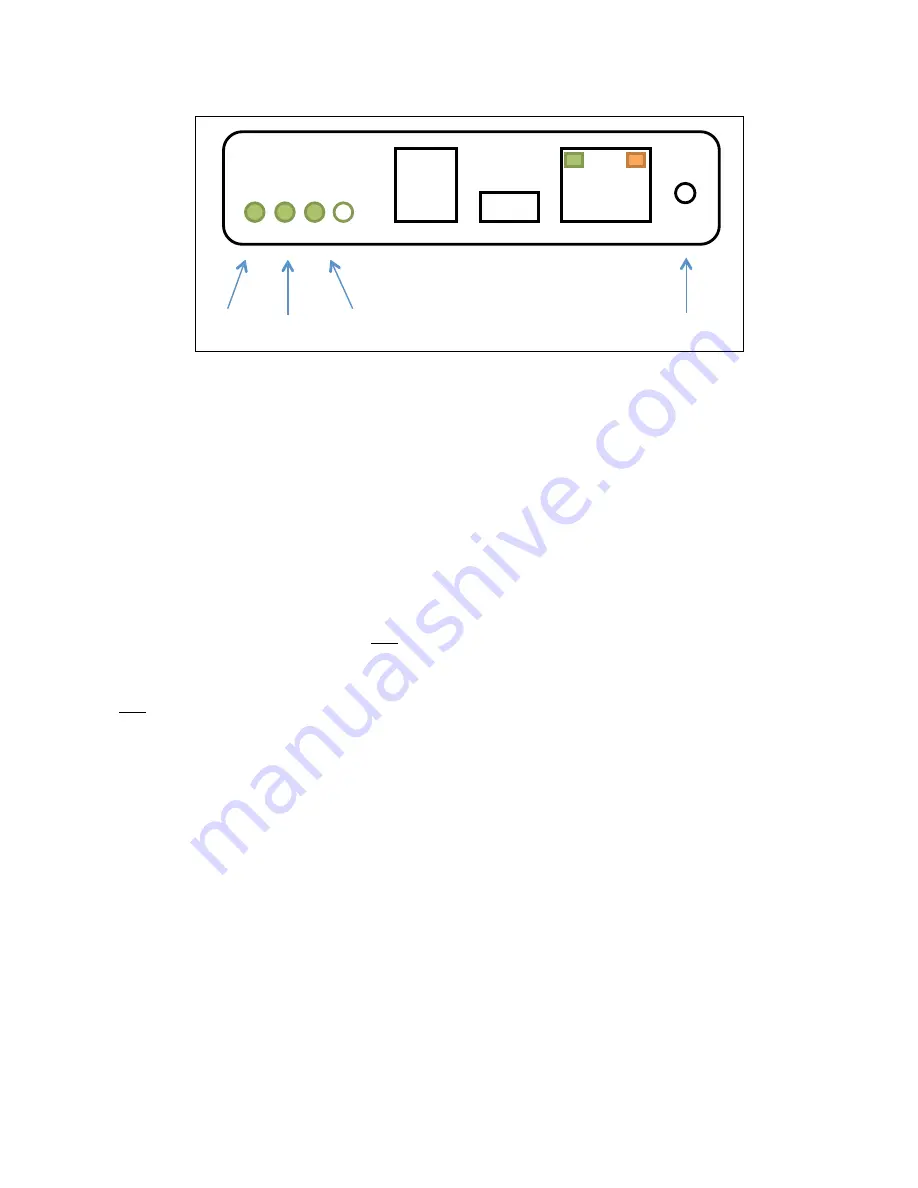
Internet Gateway Status Lights
The image below shows the bottom view of the Internet Gateway module.
The Internet Gateway has three main status lights.
The ‘Alive’ status light flashes once every two seconds to indicate that the module is powered and operating correctly.
The ‘Connected’ status light provides information about whether the Internet Gateway is/was able to connect to the
myPool Remote servers.
•
When this light is off, the Internet Gateway has not yet attempted to connect to the myPool Remote servers
(such as just after powering up).
•
When this light is solidly illuminated (not flashing), then the Internet Gateway is currently connected to the
myPool Remote servers.
•
When this light is flashing, the Internet Gateway is no longer connected to the myPool Remote servers. If it is
giving a single flash, then the connection to the servers was closed normally. If it is giving a double-‐flash, then
the connection to the servers was terminated due to an error.
The ‘Wi-‐Fi’ light indicates the status of the wireless connection. When this light is off, there is no wireless connection.
When this light is lit, it means that the Internet Gateway is properly connected to the pool owner’s wifi network. It will
blink briefly when the Internet Gateway is sending or receiving information over the wireless network. Please note that
this indicator is only giving the status of the local connection to the wireless network. The status for the connection to the
myPool Remote servers is still given by the ‘Connected’ indicator.
The Ethernet connector has two in-‐built indicators. The orange indicator is illuminated when the Ethernet connection is
properly connected to the pool owner’s Ethernet network. Please note that this indicator is only giving the status of the
local connection to the Ethernet network. The status for the connection to the myPool Remote servers is still given by the
‘Connected’ indicator. The green indicator blinks when there is data being sent or received on the Ethernet network.
Connected
Wifi
Alive
Reset switch
RJ12
To Pool
System
RJ45
To Ethernet
Summary of Contents for Viron Connect 10
Page 12: ...12 g Choose heater status if installed h Choose active lighting zones if installed...
Page 16: ...16...
Page 21: ...21 76mm centers...
Page 43: ...43 Section 11 Touch Screen Installation Instructions cont...
Page 44: ...44 Section 11 Touch Screen Installation Instructions cont...
Page 45: ...45 Section 11 Touch Screen Installation Instructions cont...
Page 56: ...56...
Page 74: ......
Page 75: ......
Page 76: ......


