Ascotel® IntelliGate® 2025/2045/2065 as of I7.9
58
Installation
sy
d-
020
4/1.
7
– I7.
9
– 1
2
.2009
[1]
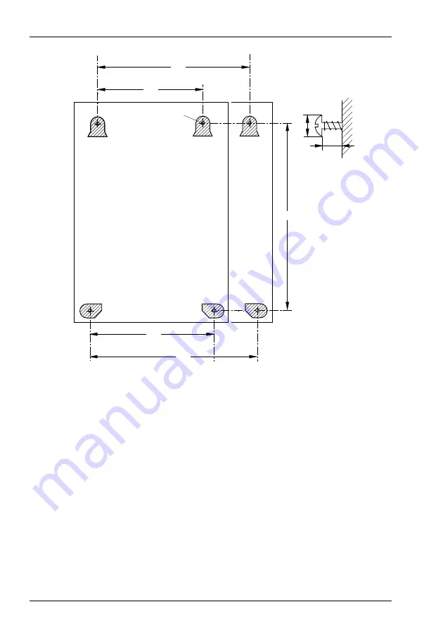
Dimensions of the basic system 2025/2045
[2]
Dimensions of the basic system 2065
Fig. 14
Dimensional drawing for wall-mounting of the PBX
To mount the basic system on a wall, proceed as follows:
1.
Mark out the position of the 4 screws as shown in the dimensional drawing for
the wall mounting of the PBX.
2.
Fit the screw dowels. Take note of the weight and technical data (see
).
3.
Fit the upper suspending screws.
4.
Suspend the PBX housing onto the suspending screws, with the mainboard pre-
installed and the cover open.
5.
Use the screws to secure the lower half of the housing to the wall.
6.
Fit the cover.
220
390
Ø4
haz1
101aaxxa0
∅
10
4 mm
[1]
345
[2]
260
[1]
385
[2]


