


Ascotel® IntelliGate® 2025/2045/2065 as of I7.9
148
Installation
sy
d-
020
4/1.
7
– I7.
9
– 1
2
.2009
4. 7. 5. 6
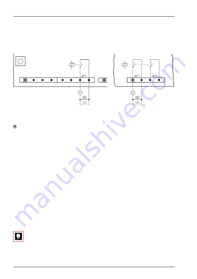
General bell
Connection via potential-free relay contact
[1]
External ringing voltage source
[2]
Maximum contact loading (as of MBS-2, MBL-2): DC max.100V / 30W, AC max.100Vrms / 62,5 VA
[3]
On mainboard2065 the general bell can be connected either on Pin 1/2 or Pin 3/4
= Pin 1
Fig. 84
Connecting the general bell to the central relay with floating contacts on the 2025/2045 main-
board (left) and 2065 mainboard (right)
The relay on the mainboard can only be used if there is an external ringing voltage
source. The maximum number of general bells connected in parallel depends on
the power of the ringing voltage source.
It is possible to use commercial auxiliary bells designed for connection in parallel to
analogue terminals as a general bell.
Connection via Analogue Terminal interface a/b
One analogue terminal interface per system can be configured in such a way that it
is also used for connecting a general bell. This eliminates the need for an external
ringing voltage source. However the impedance of the connected general bell (or
total impedance in the case of several devices connected in parallel) must not fall
below 1 k
Ω
(see also “General bell on an analogue terminal interface” in the Fea-
tures System Manual).
Tip
Both connection types can also be combined if several general bells are
used.
b/a
[1]
[2]
b/a
b/a
haz1150aaxxc0
[1]
[2]
[3]
2025 / 2045
2065


