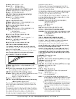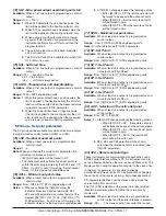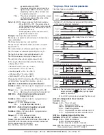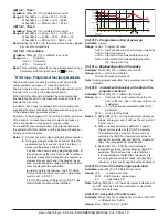
Ascon Tecnologic - KX Line - ENGINEERING MANUAL -Vr.4.0
PAG. 30
Appendix A
]
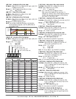
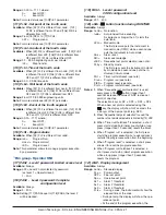
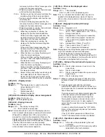
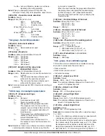
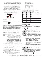
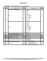
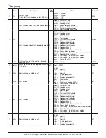
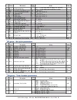
inP GROuP - Main and auxiliary input configuration
no. Param.
Description
Dec.
Point
Values
Default
1
SEnS
Sensor selection (according to the HW)
Model C
0
J = TC J,
crAL = TC K,
S = TC S,
r = TC R,
t = TC T,
ir.J = IRS J,
ir.cA = IRS K,
Pt1 = RTD Pt100,
Pt10 = RTD Pt1000,
0.60 = 0... 60 mV,
12.60 = 12... 60 mV,
0.20 = 0... 20 mA,
4.20 = 4... 20 mA,
0.5 = 0... 5 V,
1.5 = 1... 5 V,
0.10 = 0... 10 V,
2.10 = 2... 10 V
J
Model E
J = TC J,
crAL = TC K,
S = TC S,
r = TC R,
t = TC T,
ir.J = IRS J,
ir.cA = IRS K,
Ptc = TC KTY81-121,
ntc = NTC 103-AT2,
0.60 = 0... 60 mV,
12.60 = 12... 60 mV,
0.20 = 0... 20 mA,
4.20 = 4... 20 mA,
0.5 = 0... 5 V,
1.5 = 1... 5 V,
0.10 = 0... 10 V,
2.10 = 2... 10 V
2
dp
Decimal Point Position (linear inputs)
0
0... 3
0
Decimal Point Position (different than linear inputs)
0/1
3
SSC
Initial scale read-out for linear inputs
dp
-1999... 9999
0
4
FSc
Full Scale Readout for linear inputs
dp
-1999... 9999
1000
5
unit
Engineer unit
°C/°F
°C
6
Fil
Digital filter on the measured value
1
0 (= OFF)... 20.0 s
1.0
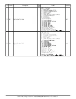
7
inE
Sensor error used to enable the safety output
value
or = Over range
ou = Under range
our = Over and under range
our
8
oPE
Safety output value (% of the output)
-100... 100
0
9
IO4.F
I/O 4 function
on =
Output used as PWS for TX,
out4 = Output 4 (digital output 4),
dG2c = Digital input 2 driven by contact,
dG2U = Digital input 2 driven by voltage
out4

