Ascon Tecnologic - KX Line - ENGINEERING MANUAL -Vr.4.0
PAG. 18
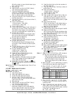
as remote set point (RSP).
trin =
The value coming from serial link will be
algebraically added to the local set point
selected by A.SP and the sum becomes
the operative set point.
PErc = The value coming from serial will be scaled
on the input range and this value will be
used as remote set point.
Note:
A [83] SPrt change produces the following actions:
•
When [83] SP.rt = rSP - the remote set point
will be forced to be equal to the active set point
•
When [83] SP.rt = trin - the remote set point
will be forced to zero
•
When [83] SP.rt = PErc - the remote set
point will be forced to zero
Example:
A 6 zone reflow-oven for PCB.
The master unit sends its set point value to 5 other zones
(slave controllers).
The Slave zones use it as a set point trim.
The first zone is the master zone and it uses a set point
equal to 210°C.
The second zone has a local set point equal to -45°C.
The third zone has a local set point equal to -45 (°C).
The fourth zone has a local set point equal to -30.
The fifth zone has a local set point equal to +40.
The sixth zone has a local set point equal to +50.
In this way, the thermal profile will be the following:
–
Master SP = 210°C;
–
Second zone SP = 210 -45 = 165°C;
–
Third zone SP = 210 -45 = 165°C;
–
Fourth zone SP = 210 - 30 = 180°C;
–
Fifth zone SP = 210 + 40 = 250°C;
–
Sixth zone SP = 210 + 50 = 260°C.
Changing the SP of the master unit, all the other slave units
will immediately change their operative set point.
[84] SPLr - Local/remote set point selection
Available:
When at list one output is programmed as control
output.
Range:
Loc =
Local set point selected by [82] A.SP;
rEn =
Remote set point (coming from serial link).
[85] SP.u - Rate of rise for positive set point
change
(ramp up)
Available:
When at list one output is e programmed as
control output.
Range:
0.01... 99.99 units per minute;
inF =
ramp disabled (step transfer).
[86] SP.d - Rate of rise for negative set point
change
(ramp down)
Available:
When at list one output is e programmed as
control output.
Range:
0.01... 99.99 units per minute;
inF =
ramp disabled (step transfer).
General note about remote set point: when the remote set
point (RSP) with trim action is programmed, the local set
point range becomes the following:
from [76] SPLL+ RSP to [77] SPHL - RSP
]
tin group - Timer function parameters
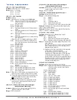
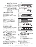
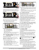
Five timer types are available:
Delayed start with a delay time and a “end of cycle” time.
Start
OUT
off
Tr.t1
Tr.t2
off
ON
–
Setting tr.t2 = Inf the timer out remains in ON condition
until a reset command is detected.
Start
OUT
ON
off
Tr.t1
Tr.t2 = inF
off
Reset
Delayed start at power up with a delay time and a “end of
cycle” time.
Start
OUT
PWR UP
off
Tr.t1
Tr.t2
off
ON
Feed-through.
Start
OUT
Tr.t1
off
Reset
ON
Asymmetrical oscillator with start in OFF.
Start
OUT
ON
off
Tr.t2
ON
off
Tr.t1
Tr.t1
Tr.t2
ON
off
Tr.t1 Tr.t2
Reset
Asymmetrical oscillator with start in ON.
Start
OUT
ON
off
Tr.t2
off
Tr.t1
Tr.t1
Tr.t2
off
Tr.t1 Tr.t2
Reset
ON
ON
Notes: 1.
The instrument can receive the start, hold and
reset commands by
button, by logic inputs
and/or by serial link.
2.
An HOLD command can suspend the time count.
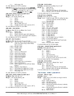
[87] tr.F= Independent timer function
Available:
Always.
Range:
nonE = Timer not used
i.d.A = Delayed start timer
i.uP.d = Delayed start at power up
i.d.d = Feed-through timer
i.P.L = Asymmetrical oscillator with start in OFF
i.L.P = Asymmetrical oscillator with start in ON
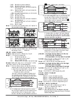
[88] tr.u - Engineering unit of the time
Available:
When [87] tr.F is different form nonE.
Range:
hh.nn = Hours and minutes
nn.SS = Minutes and seconds
SSS.d = Seconds and tenth of seconds
Note:
When the timer is running, you can see the value of
this parameter but you can NOT modify it.

