


Ascon Tecnologic - KX Line - ENGINEERING MANUAL -Vr.4.0
PAG. 10
]
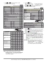
out Group - Output parameters
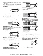
[12] o1.t - Out 1 type (KX3 only)
Available:
When the out 1 is a linear output.
Range:
0-20 = 0... 20 mA
4-20 = 4... 20 mA
0-10 = 0... 10 V
2-10 = 2... 10 V
[13] o1.F - Out 1 function
Available:
Always
Range: •
When the out 1 is a linear output (
KX3 only
)
nonE = Output not used. With this setting the status
of the this output can be driven directly
from serial link;
H.rEG = Heating output;
c.rEG = Cooling output.
r.inP = Analogue retransmission of the measured
value.
r.Err = Analogue retransmission of the measured
error (PV-SP).
r.SP = Analogue retransmission of the operative
set point.
r.SEr = Analogue retransmission of a value caming
from serial link.
•
When the out 1 is a digital output (relay or SSR)
nonE = Output not used. With this setting the sta-
tus of the this output can be driven directly
from serial link.
H.rEG = Heating output
c.rEG = Cooling output
AL =
Alarm output
t.out = Timer output
t.HoF = Timer out - OFF in Hold
P.End = Program end indicator
P.HLd = Program hold indicator
P. uit = Program wait indicator
P.run = Program run indicator
P.Et1 = Program Event 1
P.Et2 = Program Event 2
or.bo = Out-of-range or burn out indicator
P.FAL = Power failure indicator
bo.PF = Out-of-range, Burnout and Power failure
indicator
St.By = Stand By status indicator
diF1 = Out1 repeates the digital input 1 status
diF2 = Out1 repeates the digital input 2 status
on =
Out1 always ON.
Notes: 1.
When two or more outputs are programmed in the
same way, these outputs will be driven in parallel.
2.
The power failure indicator will be reset when the
instrument detect an alarm reset command by
key, digital input or serial link.
3.
When no control output is programmed, all the
relative alarm (when present) will be forced to
“nonE” (not used).
[14] A.o1L - Initial scale value of the analogue
retransmission (KX3 only)
Available:
When Out 1 is a linear output and [13] O1F is
equal to r.IMP, r.Err, r.SP or r.SEr
Range:
-1999 to [15] Ao1H.
[15] A.o1H - Full scale value of the analogue
retransmission (KX3 only)
Available:
When Out 1 is a linear output and [13] O1F is
equal to r.IMP, r.Err, r.SP or r.SEr
Range:
[14] Ao1L to 9999.
[16] o1.AL - Alarms linked up with the out 1
Available:
When [13] o1F = AL
Range:
0... 63 with the following rules:
+1 =
Alarm 1
+2 =
Alarm 2
+4 =
Alarm 3
+8 =
Loop break alarm
+16 = Sensor break (burn out)
+32 = Overload on Out 4 (short circuit on the Out4)
Example 1:
Setting 3 (2+1) the output will be driven by the
alarm 1 and 2 (OR condition).
Example 2:
Setting 13 (8+4+1) the output will be driven by
alarm 1 + alarm 3 + loop break alarm.
[17] o1.Ac - Out 1 action
Available:
When [13] o1F is different from “nonE”
Range:
dir =
Direct action
rEU = Reverse action
dir.r =
Direct action with revers LED indication
rEU.r = Reverse action with reverse LED indication.
Notes: 1.
Direct action: the output repeats the status of the
driven element.
Example: the output is an alarm output with direct
action. When the alarm is ON, the relay will be
energized (logic output 1).
2.
Reverse action: the output status is the opposite
of the status of the driven element.
Example: the output is an alarm output with
reverse action. When the alarm is OFF, the relay
will be energized (logic output 1). This setting is
usually named “fail-safe” and it is generally used in
dangerous process in order to generate an alarm
when the instrument power supply goes OFF or
the internal watchdog starts.
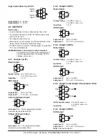
[18] o2F - Out 2 function
Available:
When the instrument has out 2 option.
Range:
nonE = Output not used. With this setting the status
of the this output can be driven directly
from serial link.
H.rEG = Heating output
c.rEG = Cooling output
AL =
Alarm output
t.out = Timer output
t.HoF = Timr out - OFF in Hold
P.End = Program end indicator
P.HLd = Program hold indicator
P. uit = Program wait indicator
P.run = Program run indicator
P.Et1 = Program Event 1
P.Et2 = Program Event 2
or.bo = Out-of-range or burn out indicator
P.FAL = Power failure indicator
bo.PF = Out-of-range, Burnout and Power failure
indicator
St.By = Stand By status indicator
diF1 = Out2 repeates the digital input 1 status
diF2 = Out2 repeates the digital input 2 status


