Ascon Tecnologic - KX Line - ENGINEERING MANUAL -Vr.4.0
PAG. 6
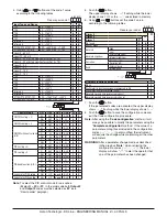
4. Using
and
buttons set the code 1 value
according to the following tables.
L M N O
Prepare your code 1
Input Type and Range
L
M
TC J
-50... +1000°C
0
0
TC K
-50... +1370°C
0
1
TC S
-50... 1760°C
0
2
TC R
-50... +1760°C
0
3
TC T
-70... +400°C
0
4
Infrared J
-50... +785°C
0
5
Infrared K
-50... +785°C
0
6
PT 100/PTC KTY81-121
-200... +850°C/-55... +150°C
0
7
PT 1000/NTC 103-AT2
-200... +850°C/-50... +110°C
0
8
Linear 0... 60 mV
0
9
Linear 12... 60 mV
1
0
Linear 0... 20 mA (this selection forces Out 4 = TX)
1
1
Linear 4... 20 mA (this selection forces Out 4 = TX)
1
2
Linear 0... 5 V
1
3
Linear 1... 5 V
1
4
Linear 0... 10 V
1
5
Linear 2... 10 V
1
6
TC J
-58... +1832°F
1
7
TC K
-58... +2498°F
1
8
TC S
-58... 3200°F
1
9
TC R
-58... +3200°F
2
0
TC T
-94... +752°F
2
1
Infrared J
-58... +1445°F
2
2
Infrared K
-58... +1445°F
2
3
PT 100/PTC KTY81-121
-328... +1562°F/-67... +302°F
2
4
PT 1000/NTC 103-AT2
-328... +1562°F/-58... +230°F
2
5
L M N O
c%d1
:
Control mode
OP1
OP2
OP3
OP4
N
O
ON/OFF heating = H
H
AL1
AL2
AL3
0
0
NU
AL1
AL2
H
0
1
ON/OFF cooling = C
C
AL1
AL2
AL3
0
2
NU
AL1
AL2
C
0
3
ON/OFF with neutral zone
(H/C)
H
C
AL2
AL3
0
4
H
AL1
AL2
C
0
5
C
H
AL2
AL3
0
6
NU
H
AL2
C
0
7
C
AL1
AL2
H
0
8
NU
C
AL2
H
0
9
PID heating = H
H
AL1
AL2
AL3
1
0
NU
AL1
AL2
H
1
1
PID cooling = C
C
AL1
AL2
AL3
1
2
NU
AL1
AL2
C
1
3
PID double action (H/C)
H
C
AL2
AL3
1
4
H
AL1
AL2
C
1
5
C
H
AL2
AL3
1
6
NU
H
AL2
C
1
7
C
AL1
AL2
H
1
8
NU
C
AL2
H
1
9
Servomotor PID heating
NU
UP
down
AL3
2
0
Servomotor PID cooling
NU
UP
down
AL3
2
1
Note:
To select the PID control mode for servodrive
(
N
plus
O
=
20
or
21
), in the order code both
Output 2
and
Output 3
codes must be selected as “
M
” (see
“How to order” pargraph).
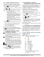
5. Push the
button.
The upper display shows
cod2
flashing while the lower
display shows
0000
or the
cod2
value stored in memory.
6. Using
and
buttons set the code 2 value
according to the following tables.
P Q R S
Prepare your code 2
Alarm 3
R
Alarm 2
Q
Alarm 1
P
Not used
0
0
0
Sensor break
1
1
1
Absolute
High
2
2
2
Low
3
3
3
Absolute High/Low
External High/Low
4
4
4
Internal High/Low
5
5
5
Deviation
Deviation high
6
6
6
Deviation low
7
7
7
Band
External band
8
8
8
Internal band
9
9
9
P Q R S
c%d2
:
Auxiliary functions activation
S
None
0
Wattmeter (instantaneous power expressed in W)
1
Wattmeter (energy expressed in Wh)
2
Absolute worked time (expressed in days)
3
Absolute worked time (expressed in hours)
4
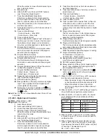
7. Push the
button.
If the just entered codes are accepted, the upper display
shows
code
flashing while the lower display shows
good
.
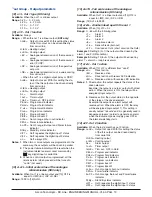
8. Push the
button to save the configuration code and
exit the Code configuration procedure.
Note:
After using the “
Code configuration
” method, it will
always be possible to modify the parameters using the
“
Complete configuration
” method. If the value of a
parameter among those included in the configuration
codes (
cod1
-
cod2
) gets modified, the instrument
will acquire the change while maintaining all the other
parameters.
wARNING!
After a parameter change made as described
in the previous “
Note
”, when retrieving the
configuration codes (
cod1
-
cod2
), the lower
display will show “
oFF
” to alert the operator that
one of the parameters has been changed.


