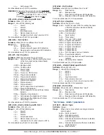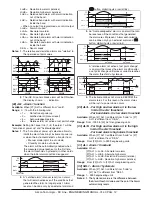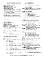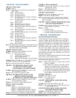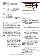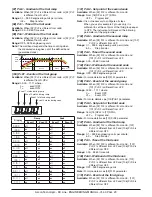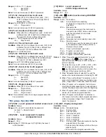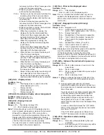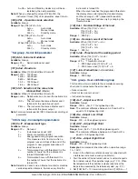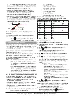
Ascon Tecnologic - KX Line - ENGINEERING MANUAL -Vr.4.0
PAG. 9
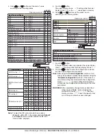
When the contact is closed the instrument oper-
ates in stand by mode.
5
Manual mode
6
HEAt with SP1 and CooL with “SP2” [status]
(see “Note about digital inputs”)
7
Timer Run/Hold/Reset [transition]
Short closure allows to start timer execution
and to suspend it while a long closure (longer
than 10 seconds) allows to reset the timer.
8
Timer Run [transition] a short closure allows to
start timer execution.
9
Timer reset [transition] a short closure allows to
reset timer count.
10
Timer run/hold [Status]
- Contact closure = timer RUN
- Contact open = timer Hold
11
Timer run/reset [status]
12
Timer run/reset with a special “lock” at the end of
the time count (in order to restart the time count
the instrument must detect a run command co-
ming from serial link keyboard or digital input 2).
13
Program Run [transition]
The first closure allows to start program execu-
tion but a second closure restart the program
execution from the beginning.
14
Program Reset [transition]
A contact closure allows to reset program execution.
15
Program Hold [transition]
The first closure allows to hold program exe-
cution and a second closure continue program
execution.
16
Program Run/Hold [status]. When the contact
is closed the program is running.
17
Program Run/Reset [status]
Contact closed - Program run
Contact open - Program reset
18
Sequential set point selection [transition]
(see “Note about digital inputs”)
19
SP1/SP2 selection [status]
20
Binary selection of the set point made by digital
input 1 (less significant bit) and digital input 2
(most significant bit) [status].
21
Digital input 1 will work in parallel with
but-
ton while digital input 2 will work in parallel with
the
button.
Note:
When [11] diF2 is not available the item 20 and 21 are
not visible.
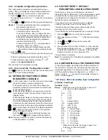
[11] diF2 - Digital input 2 function
Available:
When [9] Io4.F = diG2.
Range: oFF
= No function
1
Alarm Reset [status]
2
Alarm acknowledge (ACK) [status].
3
Hold of the measured value [status].
4
Stand by mode of the instrument [status]
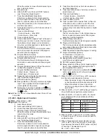
When the contact is closed the instrument ope-
rates in stand by mode.
5
Manual mode
6
HEAt with SP1 and CooL with “SP2” [status]
(see “Note about digital inputs”)
7
Timer Run/Hold/Reset [transition]
Short closure allows to start timer execution
and to suspend it while a long closure (longer
than 10 seconds) allows to reset the timer.
8
Timer Run [transition] a short closure allows to
start timer execution.
9
Timer reset [transition] a short closure allows to
reset timer count.
10
Timer run/hold [Status]
- Contact closure = timer RUN
- Contact opend = timer Hold
11
Timer run/reset [status]
12
Timer run/reset with a special “lock” at the end
of the time count (in order to restart the time
count the instrument must detect a run com-
mand coming from serial link keyboard or digital
input 2).
13
Program Run [transition]
The first closure allows to start program execu-
tion but a second closure restart the program
execution from the beginning.
14
Program Reset [transition]
A contact closure allows to reset program execution.
15
Program Hold [transition]
The first closure allows to hold program execution
and a second closure continue program execution.
16
Program Run/Hold [status]
When the contact is closed the program is running.
17
Program Run/Reset [status]
Contact closed - Program run
Contact open - Program reset
18
Sequential set point selection [transition]
(see “Note about digital inputs”)
19
SP1/SP2 selection [status]
20
Binary selection of the set point made by digital
input 1 (less significant bit) and digital input 2
(most significant bit) [status].
21
Digital input 1 will work in parallel with the
button while digital input 2 will work in parallel
with the
button.
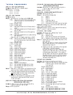
Notes: 1.
When [10] diF1 or [11] diF2 (e.g. diF1) are equal
to 6 the instrument operates as follows:
•
When the contact is open, the control action is
an heating action and the active set point is SP.
•
When the contact is closed, the control
action is a cooling action and the active set
point is SP2.
2.
When [10] diF1 = 20, [11] diF2 setting is forced to
20 and diF2 cannot perform another function.
3.
When [10] diF1 = 20 and [11] diF2 = 20, the set
point selection will be in accordance with the
following table:
Dig In1
Dig. In2
Operative set point
Off
Off
Set point 1
On
Off
Set point 2
Off
On
Set point 3
On
On
Set point 4
4.
When [10] diF1 is equal to 21, [11] diF2 setting
is forced to up.du (21 value) and cannot perform
another function.
5.
When a “Sequential set point selection” is used
(diF1 or diF2 = 18), every closure of of the logic
input increase the value of SPAT (active set point)
of one step. The selection is cyclic:
SP -> SP2 -> SP3 -> SP4.


