background image


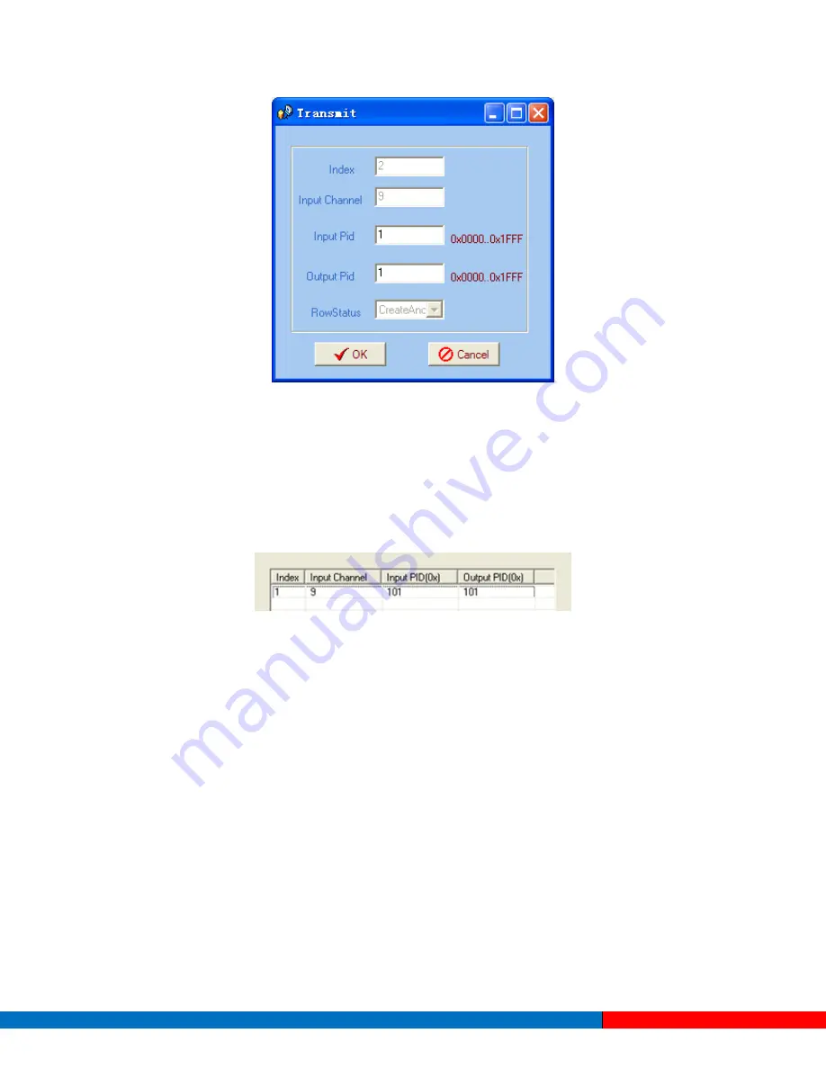
Input PID and Output PID 

The Old (Input) PID is the PID number in the TS from a given Port. The corresponding New (output) PID 
number could be same as the input PID number, or it could also be different if a PID remapping is 
needed. 

Modify the data as needed and click 

OK

 to confirm. The PID then will then be bypassed and listed in the 

table as shown below. 


Users can also modify or delete the added PID through the corresponding buttons on the right. 

4.3.3.3


NIT Parameters 

NIT: Network Information Table. 

The NIT table is a very important table for describing the network and TS. Users can set the parameters 
of the output NIT table in this interface. 

Solutions Provider for FTTx, RFoG and HFC              www.ascentcomtec.com 

Page 36 of 43 


Summary of Contents for ACT EC2400

Page 1: ...ACT EC2400 HD Encoder User Guide Revision A...

Page 2: ...strictly forbidden This document is produced to assist professional and properly trained personnel with installation and maintenance issues for the product The capabilities system requirements and or...

Page 3: ...llation Preparation 8 2 3 Wire s Connection 10 2 4 Signal Cable Connection 10 Chapter 3 Operation 13 3 1 Initializing 13 3 2 General Settings 13 Chapter 4 SNMP Operation 24 4 1 Installation 24 4 2 Sof...

Page 4: ...ign makes the device widely used in varieties of digital distribution systems Supports AVC H 264 High Profile Level 4 0 video encoding Supports advanced video pretreatment algorithm Supports MPEG 1 La...

Page 5: ...LC AAC Sampling rate 48 kHz Resolution 24 bit Bitrate 64 Kb s 384 Kb s each channel Multiplexing 1 ASI input multiplexed and 4 encoding channel SPTS output 2 ASI outputs BNC interface MPTS and 4 SPTS...

Page 6: ...Screen 2 Indicators Power Indicator TS in Input Lock Indicator CH1 TS out CH4 TS out device starts to encode and output TS CH1 Alarm CH4 Alarm device has stopped encoding or there is an encoding error...

Page 7: ...4 HDMI Input Ports EC2400 HDMI 4 SDI Input Ports EC2400 SDI 2 ASI Input Port 3 2 ASI Output Ports 4 Data Port for IP Signal Output 5 NMS Network Management Port 6 Power Switch and Socket 7 Grounding P...

Page 8: ...steps to install the device The details of installation will be described in this chapter Users can also refer to the rear panel chart in Chapter 1 during the installation The main contents of this ch...

Page 9: ...independent of each other Device power requires AC power 220V 50 Hz Please check carefully before running Good grounding designs are the basis of reliability and stability for these devices Good groun...

Page 10: ...nsert one end into the power supply socket and insert the other end to an AC power source Connecting Grounding Wire The grounding resistance should be less than 1 Caution Before connecting power cord...

Page 11: ...d its connection are illustrated as follows User can find the ASI output interface on the device according to the connector mark described on the rear panel illustration in section 1 6 and then connec...

Page 12: ...e which can handle IP signal inputs The encoder s DATA connection is illustrated as follows Users can find the NMS interface on the device according to the connector mark described on the rear panel i...

Page 13: ...e system will ask users whether or not they want to save present settings If not the LCD will display the current configuration state At the Factory Configuration page users can press the ENTER key to...

Page 14: ...4 so this manual only explains the process for one channel After pressing the ENTER key the LCD will display the following page 1 1 Encoder 1 1 2 Encoder 2 1 3 Encoder 3 1 4 Encoder 4 After users ente...

Page 15: ...e H 264 High Profile code format and the Main Profile code format are the available options Level User can select the H 264 level at this menu The option with brackets is the current choice 3 2 1 2 Au...

Page 16: ...fect 1 1 2 1 Bit rate 01 03 64 Kbps 96Kbps 112Kbps 128Kbps 1 1 2 1 Bit rate 02 03 160 Kbps 192Kbps 224Kbps 256Kbps 1 1 2 1 Bit rate 03 03 320 Kbps 384Kbps Audio Format Settings AAC Advanced Audio Codi...

Page 17: ...u Video Audio PMT PCR PID Settings Users can set these parameters by pressing ENTER to enter these submenus The maximum PID number cannot exceed 0x1fff 1 1 3 2 Video PID 0x0101 1 1 3 3 Audio PID 0x010...

Page 18: ...sers can decide whether or not to open the multiplexing function of the device Channel Mux Under this interface users can decide whether or not to multiplex the channel encoding stream YES means that...

Page 19: ...an set device output parameters 3 2 3 1 IP Out Enable This is a new function of the encoder Users can decide whether or not to open the IP output function by pressing the ENTER key in this menu 3 1 IP...

Page 20: ...enter the main editing interface 3 3 IP Out Port 01001 3 2 3 4 Trans Stream ID Users can set the device TS ID in this interface after pressing the ENTER key to enter the main editing page 3 4 Trans St...

Page 21: ...packages by entering into the below interface Users can set the network parameters by pressing the ENTER key 4 1 IP Address 192 168 002 136 4 2 Subnet Mask 255 255 255 000 3 6 ASI Output 01 02 MPTS Ch...

Page 22: ...must modify the address through special software Otherwise the IP output data will be filtered out when the IP stream passes through the router Users can save the modification by pressing the ENTER k...

Page 23: ...ice software version and hardware version Users can select the interface language in this submenu 4 in 1 Encoder SW 0 02F HW 08 8 Language ENGLISH Solutions Provider for FTTx RFoG and HFC www ascentco...

Page 24: ...e A login interface will pop up when the software is running and gives users a prompts to input a username and password The default user name is admin with no password Users can add usernames and pass...

Page 25: ...g modifying and deleting device nodes This software provides a powerful node operation function and users can edit various parameters in the device tree for management and classification Solutions Pro...

Page 26: ...n frequency when the user clicks OK Users can also right click to pop up the shortcut menu in the device tree or in the left blank column and the corresponding dialog box will pop up by choosing Add M...

Page 27: ...will pop up when the user clicks the Add Equipment item in the Edit pull down menu on the menu row Users should follow the steps as below Input the device IP Address Input the port Input the Equipment...

Page 28: ...k should be 255 255 255 0 Users can use a ping command to confirm whether or not these two are in same network 1 The default IP of the EC2400 HD Encoder is 192 168 2 136 You can check its IP address i...

Page 29: ...ash memory and refresh the device s parameters according to the loaded values by clicking on Alternatively users can click the button on the toolbar to pop up the save file dialog box which gives a pr...

Page 30: ...ameters audio parameters encoding system parameters output parameters etc Users can click Equipment Name on the node tree and enter into the parameters interface by clicking on and or to configure the...

Page 31: ...ct the output type from a drop down list Output Port Set the output port by modifying the value in this field Original Network ID This 16 bit field gives the label identifying the network ID of the or...

Page 32: ...of the PSI SI 4 3 1 2 Video Parameters Parameters Channel CH0X If any parameter is modified click to activate the modified parameters and click to read and put into effect the current device s activat...

Page 33: ...mation Refreshes the output terminal and retrieves the output information Multiplexes the input programs to the output channels after selecting the target program with The system will automatically al...

Page 34: ...o put into effect the modification The parsing overtime value 4 3 3 1 PID Filter Table Users can operate the PID filter in this table by checking the checkboxes of corresponding items and clicking Con...

Page 35: ...ut stream 4 3 3 2 PID Pass Users can choose to bypass input PID in this interface Occasionally there are PIDs which won t belong to any program such as EPG NIT tables and so on but users might want to...

Page 36: ...ick OK to confirm The PID then will then be bypassed and listed in the table as shown below Users can also modify or delete the added PID through the corresponding buttons on the right 4 3 3 3 NIT Par...

Page 37: ...allow users to insert a private description into the output TS The private description includes two parts One is the descriptor tag and the other is the descriptor information The Descriptor Tag is a...

Page 38: ...k The interface will be shown as below after the NIT parameters have been added The Modify button will open a window allowing users to modify selected items in the NIT The Delete button will remove th...

Page 39: ...configuration and will restore the last saved configuration if the device reboots To save the configuration permanently it is necessary to make modifications using Remote Save on the toolbar as expla...

Page 40: ...OK button to confirm The indicator light will turn red which means the equipment has disconnected Users can then refer to the below prompts to edit the property by inputting the new IP to reconnect t...

Page 41: ...l users and passwords can be added as needed Click Setting in the menu bar and select User Setting in the drop down list to open the dialog box shown below Select Edit Information by marking the check...

Page 42: ...other heat sink bores Check the input AC within the power supply working range and make sure the connection is secure before switching on the device Check if the RF output level varies within a tolera...

Page 43: ...WY 82001 USA Phone 86 21 60232616 Phone 1 203 816 5188 EUROPE VIETNAM Pfarrer Bensheimer Strasse 7a 15 F TTC Building Duy Tan Street CauGiay Dist 55129 Mainz GERMANY Hanoi VIETNAM Phone 49 0 6136 926...

Reviews: