


J36
J29
1
LCD display and
touch screen
12V 5V
Shield 0,
Pmod 0 and
Pmod 1 I/O ref
5V
3V3
Shield 1,
Pmod 2 and
Pmod 3 I/O ref
Shield 0,
Pmod 0 and
Pmod 1 power
Shield 1,
Pmod 2 and
Pmod 3 power
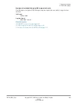
Figure 2-21 Shield and Pmod power and I/O reference voltage user-links
One user
‑
link selects 3V3 or 5V I/O operations for the Shield 0, Pmod 0, and Pmod 1 interfaces.
One user
‑
link selects 3V3 or 5V I/O operations for the Shield 1, Pmod 2, and Pmod 3 interfaces.
One user
‑
link selects 5V or 12V power for the Shield 0 interface.
One user
‑
link selects 5V or 12V power for the Shield 1 interface.
Caution
The maximum currents available at the power and reference pins are:
3V3/IOREF
1A maximum available for both Shields and all four Pmod interfaces.
5V/IOREF
1A maximum available for both Shields and all four Pmod interfaces.
12V
0.5A maximum available for both Shields.
1.3 Location of components on the MPS3 board
for the location of the user
‑
links.
Related information
A.2 Arduino Shield connectors
on page Appx-A-76
A.3 Peripheral Module (Pmod) connectors
1.3 Location of components on the MPS3 board
2 Hardware description
2.16 Arduino Shield and Pmod interfaces
100765_0000_04_en
Copyright © 2017–2020 Arm Limited or its affiliates. All rights
reserved.
2-45
Non-Confidential