


A.3
Peripheral Module (Pmod) connectors
The Pmod connectors on the MPS3 board provide digital I/O expansion capability, an alternative to the
Shield interfaces.
The four Pmod connectors enable fitting of TYPE 2A (J24/J34) and TYPE 1 (J28/J38) boards.
Connectors J24 and J28 form interface Pmod0/1 and connectors J34 and J38 form interface Pmod2/3.
The Pmod connectors carry a subset of the signals on the Arduino connectors and are wired in parallel
with them. Interface Pmod0/1 shares signals with Shield 0 interface, and Pmod2/3 shares signals with
Shield 1 interface.
Note
User
‑
links select 3V3 or 5V digital I/O operating voltages, and the digital IOREF voltages. The IOREF
voltages have maximum current limits available at the board interface pins. See
‑
links, and the maximum available IOREF
current.
Caution
The MPS3 board supports simultaneous use of Pmod and Shield expansion but you must exercise
caution when driving the shared signals.
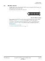
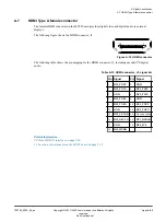
The following figure shows the Pmod connectors.
1
7
12
6
Figure A-8 Pmod connectors J24, J28, J34, and J38
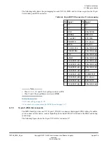
The following table shows the pin mapping for the Pmod0/1 interface connector, J24.
Table A-11 Connector J24 (Pmod0/1 interface) signal list
Pin Signal
Pin Signal
1
SH0_5V_IO10
7
SH0_5V_IO5
2
SH0_5V_IO11
8
SH0_5V_IO6
3
SH0_5V_IO12
9
SH0_5V_IO7
4
SH0_5V_IO13
10
SH0_5V_IO8
5
GND
11
GND
6
SHO_REF
12
SHO_REF
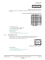
The following table shows the pin mapping for the Pmod0/1 interface connector, J28.
A Signal descriptions
A.3 Peripheral Module (Pmod) connectors
100765_0000_04_en
Copyright © 2017–2020 Arm Limited or its affiliates. All rights
reserved.
Appx-A-80
Non-Confidential