


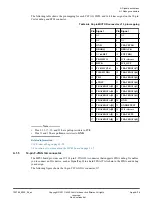


Table A-12 Connector J28 (Pmod0/1 interface) signal list
Pin Signal
Pin Signal
1
SH0_5V_IO3
7
SH0_5V_IO4
2
SH0_5V_IO1
8
SH0_5V_IO2
3
SH0_5V_IO0
9
SH0_5V_IO15
4
SH0_5V_IO9
10
SH0_5V_IO14
5
GND
11
GND
6
SHO_REF
12
SHO_REF
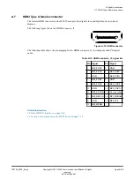
The following table shows the pin mapping for the Pmod2/3 interface connector, J34.
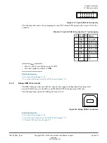
Table A-13 Connectors J34 (Pmod2/3 interface) signal list
Pin Signal
Pin Signal
1
SH0_5V_IO10
7
SH1_5V_IO5
2
SH0_5V_IO11
8
SH1_5V_IO6
3
SH0_5V_IO12
9
SH1_5V_IO7
4
SH0_5V_IO13
10
SH1_5V_IO8
5
GND
11
GND
6
SH1_REF
12
SH1_REF
The following table shows the pin mapping for the Pmod2/3 interface connector, J38.
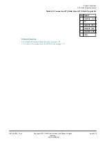
Table A-14 Connectors J38 (Pmod2/3 interface) signal list
Pin Signal
Pin Signal
1
SH0_5V_IO3
7
SH1_5V_IO4
2
SH0_5V_IO9
8
SH1_5V_IO2
3
SH0_5V_IO0
9
SH1_5V_IO15
4
SH0_5V_IO1
10
SH1_5V_IO14
5
GND
11
GND
6
SH1_REF
12
SH1_REF
Related information
2.16 Arduino Shield and Pmod interfaces
1.3 Location of components on the MPS3 board
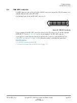
A Signal descriptions
A.3 Peripheral Module (Pmod) connectors
100765_0000_04_en
Copyright © 2017–2020 Arm Limited or its affiliates. All rights
reserved.
Appx-A-81
Non-Confidential