


The Shield and Pmod interfaces share signals, including the digital I/O. Each Shield interface has 16
digital I/O, and the four Pmod interfaces each have 8 digital I/O. See the following sections for
information on how the Shield and Pmod interfaces share the digital I/O signals:
•
.
•
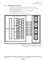
A.3 Peripheral Module (Pmod) connectors
The interfaces enable the use of off
‑
the
‑
shelf sensor interfaces, for example, WiFi, Bluetooth, proximity
sensors, and gyro sensors, to suit custom design requirements. The interfaces also enable you to add
full
‑
custom sensor modules to the system.
Shield interfaces
Each Shield interface has 16 I/O and supports the choice of 3V3 or 5V I/O, independently selectable for
each Shield using two user
‑
links.
The outputs from the digital I/O user
‑
links also act as the digital I/O voltage references for the Shields.
Other links, one for each Shield, select 5V or 12V for the power inputs, VIN0 and VIN1.
Note
The links also select I/O references and power inputs to the Pmod interfaces.
Shield and Pmod power and I/O reference voltage user-links
the use of the user
‑
links.
A 12
‑
bit ADC supports six analog channels on each Shield.
Pmod interfaces
The Pmod interfaces are an alternative to the Shield interfaces. Each Pmod expansion header has 8
digital I/O and supports the choice of 3V3 or 5V digital I/O. You can select the digital I/O using two
user
‑
links on the board. One user
‑
link selects 3V3 or 5V digital I/O operation for Pmod 0 and Pmod 1.
The other user
‑
link selects 3V3 or 5V operation for Pmod 2 and Pmod 3.
The outputs from the digital I/O user
‑
links also act as the digital I/O voltage references for the Pmod
expansion boards.
Two other links select 5V or 12V for the power inputs, VIN0 and VIN1.
Note
The links also select digital I/O references and power inputs to the Shield interfaces.
Shield and Pmod power and I/O reference voltage user-links
the use of the user
‑
links.
The locations of the Pmod connectors support the use of a dual
‑
connector board, if required.
The Pmod interfaces do not support analog I/O.
Shield and Pmod power and I/O reference voltage user-links
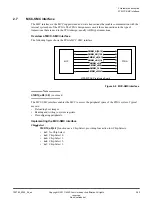
The following figure shows the user
‑
links that select I/O voltage level and power inputs to the Shield and
Pmod interfaces. The figure shows the user
‑
links that select 12V or 5V power, and 5V or 3V3 I/O
references, for the Shields.
2 Hardware description
2.16 Arduino Shield and Pmod interfaces
100765_0000_04_en
Copyright © 2017–2020 Arm Limited or its affiliates. All rights
reserved.
2-44
Non-Confidential