


A.2
Arduino Shield connectors
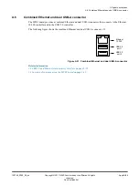
Connectors on the MPS3 board provide two Shield expansion interfaces. Each interface provides 16
digital I/O and six analog I/O.
The
Peripheral Module
interface (Pmod) connectors share some of the Shield connectors and are wired
in parallel with them. Interface Pmod0/1 shares some signals with Shield 0 interface, and Pmod2/3
shares some signals with Shield 1 interface.
Caution
The MPS3 board supports simultaneous use of Pmod and Shield expansion but you must take care when
driving the shared signals.
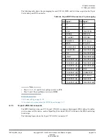
Shield 0 and Shield 1 interface connectors
The following figure shows a combined diagram of the Arduino Shield 0 and Arduino Shield 1 interfaces
on the MPS3 board.
Part of MPS3
FPGA Prototyping
Board
SH0/SH1_IO0
SH0/SH1_IO1
SH0/SH1_IO2
SH0/SH1_IO3
SH0/SH1_IO4
SH0/SH1_IO5
SH0/SH1_IO6
SH0/SH1_IO7
SH0/SH1_IO8
SH0/SH1_IO9
SH0/SH1_IO10
SH0/SH1_IO11
SH0/SH1_IO12
SH0/SH1_IO13
GND
SH0/SH1_AREF
SH0/SH1_IO14
SH0/SH1_IO15
SH0/SH1_AD5
SH0/SH1_AD4
SH0/SH1_AD3
SH0/SH1_AD2
SH0/SH1_AD1
SH0/SH1_AD0
SH0/SH1_VIN
GND
GND
5V
3V3
SH0/SH1_nRST
SH0/SH1_IOREF
N/C
SH0/SH1_nRST
GND
SH0/SH1_IO13
SH0/SH1_IO11
SH0/SH1_IO12
5V
Connector J29 (Shield interface 0)
Connector J39 (Shield interface 1)
Connector J25 (Shield interface 0)
Connector J33 (Shield interface 1)
Connector J26 (Shield interface 0)
Connector J35 (Shield interface 1)
Connector J27 (Shield interface 0)
Connector J37 (Shield interface 1)
Connector J30 (Shield interface 0)
Connector J36 (Shield interface 1)
Figure A-7 Shield 0 and Shield 1 interface connectors on the MPS3 board
Connectors J25, J26, J27, J29, and J30 form the Shield 0 interface.
Connectors J33, J35, J36, J37, and J39 form the Shield 1 interface.
A Signal descriptions
A.2 Arduino Shield connectors
100765_0000_04_en
Copyright © 2017–2020 Arm Limited or its affiliates. All rights
reserved.
Appx-A-76
Non-Confidential