


2.12
On-board user components
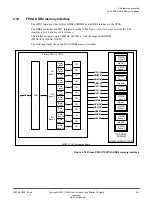
The MPS3 board provides ten user LEDs, eight user switches, and two user push buttons.
The LEDs, switches, and push buttons connect directly to the FPGA, meaning they can be used for
debug.
The following figure shows the user components on the MPS3 board.
MPS3 FPGA Prototyping Board
FPGA
USER_SW[7:0]
USER_LED[9:0]
USER_PB[1:0]
Switches
GND
PB1
PB2
1V8
LEDs
Figure 2-17 MPS3 board user components
Related information
1.3 Location of components on the MPS3 board
2 Hardware description
2.12 On-board user components
100765_0000_04_en
Copyright © 2017–2020 Arm Limited or its affiliates. All rights
reserved.
2-39
Non-Confidential