


— 1451k logic cells.
— Four UARTs (connected to a USB to serial hub for connection to the host computer).
— Support for encrypted FPGA images and Partial Reconfiguration.
• User memory system:
— Up to 8MB internal BRAM.
— microSD card interface.
— 8MB external QSPI flash.
— 4GB, 64
‑
bit external DDR4 SODIMM.
— 16GB, 8
‑
bit external eMMC.
•
Motherboard Configuration Controller
(MCC) that controls the MPS3 board, and supports board
configuration at powerup or reset:
— FPGA configuration.
— Board configuration.
— Supervises user update of the board configuration files in the configuration microSD card.
— Two hardware reset buttons, both labeled
PBRST
, and two On/Off soft reset buttons, both labeled
PBON
.
• Ethernet 10/100 port and Ethernet controller that connects to the
Static Memory Controller
(SMC)
interface in the FPGA.
• HDMI port and HDMI controller:
— Inputs 24
‑
bit RGB data from the HDLCD controller in the FPGA.
— Configured over I
2
C directly from FPGA.
— Supports an I
2
S audio connection to the FPGA.
— Drives the HDMI connector.
• Audio codec:
— Provides stereo Line In, stereo Line Out, and stereo Microphone Input In to the stacked stereo
jack audio interface.
— Configured over I
2
C from the I
2
C controller in the FPGA.
— I
2
S audio connection to the I
2
S in the FPGA.
• Shield expansion:
— Two Arduino expansion interfaces for Shields for custom peripherals or off
‑
the
‑
shelf sensor
interfaces such as WiFi, Bluetooth, Proximity detectors, or Gyro sensors.
— Each interface connects: 16 × digital 3V3 I/O or 16 × digital 5V I/O, voltage references, and six
analog inputs from each Shield.
•
Peripheral Module
(Pmod) interface expansion:
— Four Pmod expansion connectors that use the same I/O on an interface that is shared with the
Shield connectors, Type 2A/3/4 support.
— Requires Pmod adapters that provide 8 × analog 3V3 I/O, or 8 × analog 5V I/O.
• FMC
‑
HPC expansion:
— Connector to enable fitting of an
FPGA Mezzanine Card
(FMC)
High Pin Count
(HPC)
expansion card to the MPS3 board.
— A 14
‑
pin FMC configuration connector and configuration EEPROM to enable configuration of
Arm FMC boards.
• User switches, LEDs, and push buttons that connect directly to GPIO in the FPGA:
— One 8
‑
way user DIP switch.
— Ten user LEDs.
— Two user push buttons.
• System LEDs:
— Green
12V OK
LED.
— Orange
3V3 OK
LED.
— Green
PWR ON
LED.
— Green
FPGA configuration
LED.
— Green
MCC active
LED.
— Orange
Debug USB active
LED.
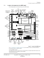
2 Hardware description
2.1 Overview of the board hardware
100765_0000_04_en
Copyright © 2017–2020 Arm Limited or its affiliates. All rights
reserved.
2-19
Non-Confidential