background image

53

DE269A

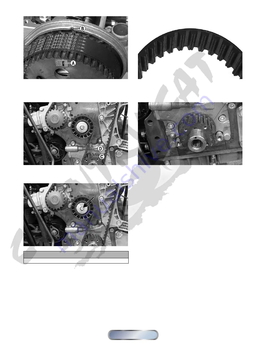
9. Check that the reference mark (C) on the timing belt

drive pulley aligns with the reference mark (D) on

the oil pump housing.

DE230A

10. Loosen the retaining nut on the timing belt idler pul-

ley; then loosen the belt and remove from the engine.

DE230B

Inspecting

1. Check the timing belt for missing cogs, cracks, or

bare cords showing. Replace if any of the conditions

are present.

DE273

2. Inspect the drive and driven pulleys for wear, burrs,

or dirt build-up between cogs. Clean and remove

burrs as required.

DE232

3. Inspect the timing belt cover for cracks, seal damage,

or signs of oil leakage. If oil is present, locate and

repair any leaks. Thoroughly clean all oil from the

timing belt cover and pulleys.

Installing

1. Check that the reference mark (C) on the timing belt

drive pulley is aligned with the reference mark (D)

on the oil pump housing and the reference mark (A)

on the camshaft drive pulley is aligned with the ref-

erence mark (B) on the cylinder head.

NOTE: If the camshaft or crankshaft has been

rotated, use the following procedure to safely realign
the reference marks.

A. Carefully rotate the crankshaft until the reference

mark (C) on the timing belt drive pulley is

approximately 90° from the reference mark (D)

on the oil pump housing.

CAUTION

Do not rotate the camshaft or valve damage could occur.

Manual

Table of Contents

Summary of Contents for 700 Diesel

Page 1: ...ollow the directive because it deals with the possibility of severe personal injury or even death A CAUTION identifies unsafe practices which may result in ATV related damage Follow the directive beca...

Page 2: ...m 97 Radiator 97 Hoses Thermostat 98 Fan 99 Water Pump 99 Troubleshooting 99 Electrical System 100 Battery 100 Testing Electrical Components 101 Switches 101 Accessory Receptacle Connector 101 Brakeli...

Page 3: ...g Free Length min 43 0 mm 1 69 in CYLINDER PISTON AND RINGS Bore x Stroke 75 x 77 6 mm 2 95 x 3 05 in Piston Ring End Gap Installed min 0 25 mm 0 0098 in Piston Ring Groove Width 1st 2nd 3rd 0 090 0 1...

Page 4: ...Arm Frame 50 68 Ball Joint Cap Screw Knuckle 35 48 Shock Absorber Frame 50 68 Shock Absorber Upper A Arm 50 68 ENGINE TRANSMISSION Part Part Bolted To Torque ft lb N m Transmission Mounting Plate Cran...

Page 5: ...s at or below 10 C 14 F use 1 diesel fuel Diesel fuel with a minimum cetane number below 42 should not be used RECOMMENDED ENGINE OIL The recommended oil to use is an oil which is rated SJ CF under AP...

Page 6: ...loth 5 Apply light oil to the upper steering post bushing and plungers of the shock absorbers 6 Tighten all nuts bolts cap screws and screws Make sure rivets holding components together are tight Repl...

Page 7: ...brakelight and headlight aim adjust or replace as necessary 8 Tighten all nuts bolts cap screws and screws mak ing sure all calibrated nuts cap screws and bolts are tightened to specifications 9 Check...

Page 8: ...Every Year or Every 1250 Miles Every 2 Years or Every 5000 Miles As Needed Battery I I C Fuses Relays PDM I I R Air Filter I R R Valve Clearance I A Muffler Spark Arrester C R Fuel Vent Hoses I R Fue...

Page 9: ...look for any pin points of light shining out of the filter medium A bright pin point of light indicates a hole and the filter element must be replaced DE028A 6 Check the safety element for signs of d...

Page 10: ...Using a suitable brush clean the carbon deposits from the screen taking care not to damage the screen NOTE If the screen or gasket is damaged in any way it must be replaced 3 Install the spark arrest...

Page 11: ...l 3 4 turn DE018 NOTE Install a new O ring each time the filter is replaced 7 Install the engine drain plug and tighten to 18 ft lb Pour the specified amount of the recommended oil in the filler hole...

Page 12: ...tighten securely Pour rec ommended lubricant into the filler hole Install the filler plug 5 Remove the transmission lubricant level stick and wipe it with a clean cloth then check the lubricant level...

Page 13: ...switch to the lights position the headlights and taillight should illuminate Test the brakelight by compressing the brake lever The brakelight should illuminate HEADLIGHT NOTE The bulb portion of the...

Page 14: ...l mark 5 cm 2 in below the horizontal mark on the aiming surface ATV 0070C 7 Adjust each headlight by turning the adjuster knob clockwise to raise the beam or counterclockwise to lower the beam CD714A...

Page 15: ...lic brake sys tem use the following procedure 1 With the master cylinder in a level position check the fluid level in the reservoir If the level in the res ervoir is not visible in the sight glass add...

Page 16: ...replaced as a set 4 To replace the brake pads use the following proce dure A Remove the wheel B Remove the cap screws securing the caliper holder to the knuckle then remove the pads PR237 C Install th...

Page 17: ...stall the plug 3 Remove the filler cap located under the service access cover and add coolant as necessary to bring coolant level to the top of the filler neck Install and tighten the filler cap DE073...

Page 18: ...t side therefore if directional arrows are printed on the V belt they must be directed rearward 2 Push the V belt down into the driven pulley approxi mately one inch then squeeze the belt together and...

Page 19: ...el filter use the following procedure 1 Remove the right front fender splash panel then using an appropriate filter wrench remove the fuel filter 2 Apply a light coat of oil to the seal ring of the ne...

Page 20: ...g the engine transmis sion SPECIAL TOOLS A number of special tools must be available to the techni cian when servicing the engine transmission NOTE Special tools are available from the Arctic Cat Serv...

Page 21: ...mission DE066A DE071A 6 Loosen the two hose clamps securing the air diverter to the inlet hoses then remove the air diverter 7 Remove the upper radiator hose from the filler neck then loosen the hose...

Page 22: ...12 Remove the fuel supply and fuel return hoses from the fuel rail DE065A 13 Disconnect the wire connectors from the temperature sensor oil pressure sensor gear position switch con nector and voltage...

Page 23: ...xhaust pipe to the exhaust manifold then remove the exhaust pipe Account for a steel gasket 18 Place a suitable block between the oil pan and frame member then remove the front engine mount cap screw...

Page 24: ...transmission can be removed for servic ing without removing the engine To remove the transmission use the following procedure 1 Remove the inner front splash shields foot pegs and forward footwells s...

Page 25: ...preferable to remove and disassemble only those components which need to be addressed and to service only those components The technician should use discretion and sound judgment NOTE The engine tran...

Page 26: ...ing then remove the governor flyweight assembly Account for a small O ring DE245A DE277 8 Remove the control spool thrust bearing and thrust washer Note the order of disassembly and keep together and...

Page 27: ...an O ring NOTE Do not loosen or remove screws D or E or fuel delivery equalization will have to be performed DE291A DE327 DE282 11 Remove the governor fork and governor spring assembly through the ope...

Page 28: ...Installing 1 Install the governor fork assembly into the cylinder head and secure with the governor fork pivot pin Tighten securely DE282 2 Using a new copper washer install the torque setting screw...

Page 29: ...nnect the throttle linkage into the throttle control lever then secure with the E clip DE249A 6 Place control spool thrust bearing and thrust washer into the governor flyweight assembly and secure the...

Page 30: ...lley to the camshaft with a washer and cap screw then using an appropri ate holding tool tighten the cap screw to 59 ft lb DE262 10 Install the timing belt see Left Side Components in this section 11...

Page 31: ...n Cooling DE077B 5 Disconnect the crankcase breather hose from the right front corner of the valve cover DE294A 6 Remove the fuel hoses from the fuel rail then plug or close off the hoses to prevent f...

Page 32: ...bands bind the rocker arms together and lift the assembly off the mounting studs being careful to keep the injector push rods with the injector it was originally installed in DE260C DE529 11 Using an...

Page 33: ...Inspecting 1 Thoroughly clean the camshaft in parts cleaning sol vent then dry with compressed air 2 Inspect each camshaft journal for scoring heat dis coloring or pitting DE298A 3 Inspect all camsha...

Page 34: ...camshaft journal diameter Measurement must not be less than minimum specification DE522 DE523 7 Using a micrometer measure and record camshaft intake exhaust and injection lobe height Measure ments mu...

Page 35: ...original positions as removed coating all components with clean engine oil Hold components in place with rubber bands DE529 Installing NOTE The flywheel end of the camshaft includes a bolt on eccentr...

Page 36: ...il to the governor assembly and install on the camshaft then hold the flyweight assembly and remove the rubber band Install a new O ring on the camshaft DE535 DE536 DE537 6 Using a new O ring install...

Page 37: ...this section 12 Place a small bead of high temperature sealant on both sides of the fuel rail seal then carefully install the valve cover with a new gasket and oil return boot Secure with existing ha...

Page 38: ...side of the valve cover 5 Disconnect the crankcase breather hose from the right front corner of the valve cover DE294A 6 Remove the fuel hoses from the fuel rail then plug or close off the hoses to pr...

Page 39: ...ber of special instruments special training and an extremely clean environment clean room therefore Arctic Cat recommends injector service be performed by a qualified diesel injection service facility...

Page 40: ...ean the fire ring sealing surface in the cylinder head taking care not to damage the pre combustion cup ring nut DE567B 5 Clean the fire ring sealing surface on the injector tip taking care not to dam...

Page 41: ...f it was removed 9 Install the unit injector retainer nuts and tighten in five steps to 15 ft lb in 3 ft lb increments DE329 10 Rotate the engine clockwise to compress the injector push rod sufficient...

Page 42: ...e is felt on the handle DE031A 18 Remove the covering from the air intake hose then start the engine and check for normal engine opera tion and look for any fuel or oil leaks 19 Install the air filter...

Page 43: ...check the clearance between the camshaft follower and cam shaft DE642A 6 To adjust the clearance loosen the jam nut A then rotate the adjuster B to obtain the specified clear ance C DE429A 7 When pro...

Page 44: ...wing procedure 1 Remove the valve cover and fuel rail see Unit Injec tors in this sub section 2 Install the Fuel Injector Timing Tool on the injector using the eccentric gasket over the check valve in...

Page 45: ...k B and note early or late injector timing NOTE If the reference mark D is left of the 13 BTDC mark B injector timing is early If it is to the right injector timing is late A Rotate the engine to perf...

Page 46: ...Engine Transmission in this section 2 Secure the engine on a suitable stand 3 Remove the timing belt see Left Side Components in this section 4 Remove the unit injectors see Top Side Compo nents in th...

Page 47: ...s spring holders and retainers to aid during assembling DE300 DE315 4 Remove the glow plugs 5 Secure the cylinder head using suitable blocks to pre vent damage to the pre combustion chambers then usin...

Page 48: ...t the head measure any warpage with the feeler gauge Check corner to corner side to side and end to end DE302 NOTE If cylinder head warpage is present the cyl inder head must be planed by a qualified...

Page 49: ...f valves valve guides or valve seats require servicing or replacement Arctic Cat recommends that the compo nents be taken to a qualified machine shop for servicing Assembling Valves 1 Thoroughly clean...

Page 50: ...toward the glow plug bore NOTE To simplify installation orientation of the pre combustion chamber install the chamber on the removal tool then place into the head Remove the tool after completing ste...

Page 51: ...adequate piston to cylinder head clearance To select the correct cylinder head gasket use the following procedure A Rotate the crankshaft until one of the pistons is at top dead center TDC as indicate...

Page 52: ...Apply clean engine oil to the threads of the cylinder head bolts washers the bolt heads and the thrust areas then install and hand tighten 7 Tighten the head bolts to 35 ft lb in 7 ft lb incre ments u...

Page 53: ...move the shift linkage from the shift arm and swing the linkage forward Account for an E clip bushing and washer 4 Loosen the alternator mounting cap screws and remove the alternator belt 5 Remove fou...

Page 54: ...damage or signs of oil leakage If oil is present locate and repair any leaks Thoroughly clean all oil from the timing belt cover and pulleys Installing 1 Check that the reference mark C on the timing...

Page 55: ...sition the handle 90 to the tensioner tab and apply 14 5 ft lb of torque Tighten the timing belt idler nut securely DE234A DE222A 4 Rotate the engine in the direction of rotation clock wise facing the...

Page 56: ...coolant bypass hose from the water pump then remove four cap screws securing the water pump and remove the water pump 4 Thoroughly clean all gasket material from the engine block and water pump Servi...

Page 57: ...seal bore DE237 NOTE If there is a groove worn in the crankshaft where the seal contacts press the seal into the bore an additional 2 mm 0 080 in Servicing NOTE The oil pump is a non serviceable compo...

Page 58: ...the seat and left side engine cover 2 Disconnect the battery B wire from the alternator then disconnect the voltage regulator control plug in DE519B 3 Loosen the alternator adjuster cap screw A and th...

Page 59: ...from the frame for this procedure FLYWHEEL PTO V BELT HOUSING Removing 1 Remove the transmission see Removing Engine Transmission Transmission in this section 2 Using Drive Clutch Removal Tool remove...

Page 60: ...e ring gear is free to be driven from the flywheel then using a punch and hammer tap the ring gear off the flywheel DE592 3 Lay the flywheel on a flat surface with the PTO side up then place the new r...

Page 61: ...n the shift arm them remove the shift arm DE119A 4 Remove the shift shaft housing Account for a gas ket 5 Remove the shift shaft noting the match marks on the drive and driven gear plates Account for...

Page 62: ...DE663B DE663B 10 Remove the output driveshaft assembly A Account for the bearing alignment C ring in the bearing boss next to the output driven bevel gear NOTE Note the location of the bearing alignme...

Page 63: ...nsmission case 18 Remove the snap ring securing the output drive bear ing in the right side case then using appropriate bearing drivers remove the appropriate bearings DE169 DE170 Disassembling Drives...

Page 64: ...assembling Countershaft NOTE Steps 1 21 of the preceding sub sections must precede this procedure 22 Remove the high driven gear then remove the high low shift dog Account for a washer and the high dr...

Page 65: ...bushing DE154 DE155 26 Remove the low gear locking washer then rotate and remove the splined low gear retainer DE184 27 Remove the low gear Account for a washer and the low gear bearing and bushing D...

Page 66: ...or galling DE143 DE179 4 Inspect roller bearings for chipping missing rollers or discoloration DE178 DE185 5 Inspect drive and driven bevel gears for proper tooth contact chipping or discoloration of...

Page 67: ...ng DE128 11 Inspect bearings for discoloration flaking or rough ness and binding when turning 12 Inspect and thoroughly clean all bearing pockets thread bores and plug openings to remove any metal fil...

Page 68: ...hing and bear ing DE185A 4 Install the reverse driven gear onto the bearing then secure with a splined washer and snap ring NOTE Always install snap rings with the flat sharp side away from the washer...

Page 69: ...shaft until it firmly contacts the spacer DE667A 2 Install the bearing race A and bearing B onto the secondary driven shaft C making sure the bearing locating groove is directed away from the driven g...

Page 70: ...381 mm 0 005 0 015 in Correcting Backlash NOTE If backlash measurement is within the acceptable range no correction is necessary 1 If backlash measurement is less than specified remove an existing sh...

Page 71: ...l the input driveshaft DE179 DE140 DE192A 3 Install the assembled countershaft assembly taking care to position a washer on each end DE142 DE193A 4 Install the reverse shift fork then install the gear...

Page 72: ...with the case groove and install the C ring DE135A DE663D 7 Apply a thin layer of Three Bond Sealant to the mat ing surface of the right side gear case then make sure that the alignment pins and washe...

Page 73: ...Using a new gasket install the shift shaft housing and secure with existing cap screws then install the shift arm aligning the mark with the slot Tighten all fasteners securely DE119 12 Apply Three B...

Page 74: ...ponents in this sec tion 3 Remove the timing belt see Left Side Components in this section 4 Remove the cylinder head assembly see Top Side Components in this section 5 Remove the oil pump assembly se...

Page 75: ...andle carefully push against the first connecting rod until the piston connecting rod assembly is free of the cylinder bore NOTE If the piston hangs up at the top of the cyl inder it may be necessary...

Page 76: ...at the thrust bearing surface Record this measurement DE435A 17 Mark the main bearing caps and engine block for proper orientation then remove the cap screws securing the main bearing caps to the main...

Page 77: ...bear ing caps and saddles then set the caps aside in order NOTE If main bearing inserts are to be used again mark their locations for correct positioning during installing 3 Using appropriate thread t...

Page 78: ...er and dry with compressed air 7 Using a cylinder bore gauge or suitable snap gauge and micrometer measure the cylinder bore at three locations taking measurements at 45 intervals If the cylinder is f...

Page 79: ...izes Use of undersized bearings will require the crankshaft journals to be machined to the correct size by a qualified machine shop 12 Lightly coat the crankshaft journals with clean oil If no machini...

Page 80: ...ding main bearing bore The clearance must be within specifications DE609A DE614A 17 Install the bearing inserts to be used for assembly in the connecting rods then secure the connecting rod in a suita...

Page 81: ...ualified machine shop replace bushings 21 Examine the connecting rods for nicks gouges dis coloration and stress lines DE623 22 Examine the piston pin bushing for galling or discol oration If either c...

Page 82: ...s into the main bearing saddles making sure the oil holes in the inserts are aligned with the oil galleys in the saddles and the locating tabs are oriented in the reliefs DE376A 2 Install the thrust b...

Page 83: ...DE431A 6 Using Main Bearing Seal Installation Tool or 0 07 mm 0 003 in shim stock as shown slide the main bearing cap into position in the main bearing saddle being careful to keep the seals from slid...

Page 84: ...ace the oil expander ring in the 3rd bottom ring groove then install the oil scraper ring over the expander making sure the oil scraper ring end gap is not directly in line with the expander spring en...

Page 85: ...ile carefully guiding the connecting rod onto the crankshaft journal push or bump the top of the piston until the connecting rod is seated on the crank shaft DE436 21 Apply clean engine oil to the cra...

Page 86: ...return galleys DE440B DE410 27 Install new O rings on the oil sump and return pipes then apply oil soluble grease on the O rings and place the oil pan into position DE596A 28 Secure the oil pan with t...

Page 87: ...ngine is now assembled and ready for connec tion to the transmission secondary transmission 35 Install the engine transmission assembly see Install ing Engine Transmission in this section Installing E...

Page 88: ...ows are present DE479 DE488 6 Secure the driven pulley with a flat washer and nut threads coated with green Loctite 609 then tighten the nut to 125 ft lb NOTE If using a new nut ensure any bare thread...

Page 89: ...ith four cap screws Tighten to 20 ft lb DE083A 5 Raise the front of the engine and install a cap screw two flat washers and a nut securing the front mount ing bracket to the front engine mount Do not...

Page 90: ...e and gasket and secure with two copper nuts Do not tighten the nuts at this time DE587 11 Install the muffler and secure to the exhaust pipe with two springs making sure the grafoil seal is in place...

Page 91: ...lift pump and tighten the banjo fitting bolts securely DE078B 15 Install the V belt cooling fan assembly then install the V belt cooling boots to the V belt housing DE076A 16 Connect the V belt cooli...

Page 92: ...ensor connector to the speed sensor DE071A DE066A 21 Connect the shift linkage to the transmission shift arm and secure with the E clip DE064A 22 Install the front body panel and front rack then insta...

Page 93: ...e noisy Excessive valve chatter Condition Remedy 1 Valve clearance too large 2 Valve spring s weak broken 3 Rocker arm rocker arm shaft worn 4 Camshaft worn 5 Cam followers worn 1 Adjust clearance 2 R...

Page 94: ...ce service rings cylinder 3 Replace guides 4 Replace bore engine block 5 Replace valves 6 Replace seals 7 Clean replace element Problem Engine lacks power Condition Remedy 1 Valve clearance incorrect...

Page 95: ...e amount required for any particular power setting is directed back into the fuel return side of the fuel rail and routed back to the fuel filter head where it either recirculates or is returned to th...

Page 96: ...G 1 Remove the right front inner splash panel then remove the V belt cooling boot from the V belt hous ing DE061A 2 Locate the fuel solenoid mounted on top of the fuel filter head then disconnect the...

Page 97: ...nd dry with compressed air NOTE If any pin holes are noted in the fuel screen replace the fuel level sensor assembly 5 Inspect the tank cap and filler neck for chipped or broken threads 6 Inspect the...

Page 98: ...S qt under the left front of the engine then loosen the hose clamp on the coolant bypass hose 3 Remove the hose and allow coolant to drain into the drain pan A funnel or short hose can be used to dire...

Page 99: ...ant from the cooling system 2 Remove the two cap screws securing the thermostat cover housing to the thermostat housing Account for an O ring and a thermostat INSPECTING NOTE Whenever a part is worn e...

Page 100: ...ent and must be replaced as an assembly To replace the water pump see Engine Transmission Left Side Components Troubleshooting Problem Starting impaired Condition Remedy 1 Fuel contaminated 1 Drain fu...

Page 101: ...OFF position NOTE Be sure to maintain the fluid of the battery at the UPPER LEVEL Use only distilled water when adding fluid to these batteries 2 Clean the battery terminals with a solution of baking...

Page 102: ...r If any other type of meter is used readings may vary due to internal circuitry When trou bleshooting a specific component always verify first that the fuse s are good that the bulb s are good that t...

Page 103: ...ery voltage the main wiring harness is good proceed to test the switch component the connector and the switch wiring har ness for resistance RESISTANCE Switch Connector NOTE The brake lever must be co...

Page 104: ...vice located under the seat The glow plug controller relay applies 12 DC volts to the glow plugs in the pre combustion cham bers to aid in cold starting Heating time is determined by the ECT thermisto...

Page 105: ...r supply then connect the black wire from the fan connector to ground The fan should operate Fuse Block Power Distribution Module The fuses are located in a power distribution module under the seat If...

Page 106: ...If the sensor tests are within specifications the speedometer must be replaced see Controls Indi cators To replace a speed sensor use the following procedure 1 Disconnect the three wire connector from...

Page 107: ...harness DIODE Starter Button NOTE If voltage is not as specified check the con dition of the battery in the meter prior to replacing the switch A low battery will result in a low voltage read ing dur...

Page 108: ...ire in the supply harness The meter must show approxi mately 10 DC volts 6 Select the 4WD position on the front drive selector switch then connect the red tester lead to the white orange wire in the s...

Page 109: ...ection on the starter relay The meter must show battery voltage DE002B NOTE Make sure that the ignition switch is in the ON position transmission in neutral brake lock released and the emergency stop...

Page 110: ...ng a suitable pry tension the drive belt so that a 10 kg 22 lb force applied at the midway point will result in a deflection of 10 15 mm 0 4 0 6 in DE103B 3 Holding tension on the belt tighten the adj...

Page 111: ...h should be in the ON position and the brake either foot pedal or hand lever must be applied NOTE Make sure the brake lever hand and brake pedal auxiliary are properly adjusted for this proce dure 1 S...

Page 112: ...5 Emergency stop ignition switch off 6 Wiring connections loose disconnected 1 Charge replace battery 2 Replace switch 3 Replace starter assembly 4 Replace relay 5 Turn on switches 6 Connect tighten...

Page 113: ...r is located on the left side of the front drive input housing With the engine stopped and the ignition switch in the ON position a momentary whirring sound can be heard each time the front drive sele...

Page 114: ...he main harness 6 Turn the ignition switch to the ON position and check the operation by shifting the selector switch several times 7 Secure the wiring harness to the frame with a nylon cable tie then...

Page 115: ...p the end of the axle and free it from the knuckle assembly AF628D 11 Pull the steering knuckle away from the axle KX151 12 Support the axle to not allow it to drop or hang 13 Remove the lower shock b...

Page 116: ...ctuator to the gear case then remove the actuator AG925 18 Remove the lower differential mounting cap screw Account for a lock nut and washers CD026 19 Remove the upper differential mounting cap screw...

Page 117: ...mallet remove the housing Account for a gasket Remove the fork collar and spring Note the location of all the components for assem bling purposes GC015 CD106 3 Using a boot clamp pliers or suitable s...

Page 118: ...bdenum Disulphide Grease packing the boot ribs and splines then assemble allowing excess grease to freely escape Slight pressure on the boot will be present during assembly Secure with new clamps NOTE...

Page 119: ...n housing Account for the coupler fork and spring differential only GC015 2 Using a T 40 torx wrench remove the cap screws securing the differential cover Account for and make note of the ID tag locat...

Page 120: ...de KX179 KX181 Disassembling Pinion Gear NOTE Any service of the pinion gear or related bearings will require a new gear case differential housing The removal of the lock collar severely dam ages the...

Page 121: ...g using a press CC884 3 Coat a new needle bearing and the bearing pocket of a new gear case differential housing with red Loctite 271 then using a suitable driver install the bearing lightly seated ag...

Page 122: ...klash prior to any other shim ming 1 Install the existing shim or a 0 051 0 055 in shim on the gear case side of the ring gear assembly GC031A 2 Install the ring gear with shim in the gear case then w...

Page 123: ...tationary rock the ring gear assembly forward and back and record the backlash Backlash must be 0 011 0 015 in If backlash is within specifications proceed to Ring Gear End Play If backlash is not wit...

Page 124: ...gear case side of the ring gear with the chamfered side toward the ring gear then install into gear case differential housing GC031A GC020 2 Place the selected end play shim chamfered side toward the...

Page 125: ...fork assembly making sure the fork leg is facing upward Apply a small amount of oil to the gasket then install the gasket CC893 8 Place the input shaft assembly onto the gear case housing then secure...

Page 126: ...plug Tighten to 16 ft lb 3 Install the front drive actuator with the three torx head cap screws then connect the wire connector to the main wiring harness AG925 4 Install the inner fender panels 5 Ins...

Page 127: ...the knuckle and set aside 7 Remove the cap screw and lock nut securing the knuckle to the upper A arm Discard the lock nut NOTE Never reuse a lock nut Once a lock nut has been removed it must be repla...

Page 128: ...the gear case PR725A PR729B NOTE To assure proper seating of the axle give it a light pull the axle should remain clipped in place 2 Swing the knuckle up and onto the drive axle then place the knuckle...

Page 129: ...ng sure each side of the pin is flush to the hub nut CD027 7 Install the wheel and tighten to 45 ft lb steel wheels or 80 ft lb aluminum wheels 8 Remove the ATV from the support stand and release the...

Page 130: ...ar ance too small until correct specification is reached INSTALLING 1 Slide the gear case into position through the left side of the frame then secure it to the frame with cap screws and lock nuts Tig...

Page 131: ...of the pin is flush to the hub nut CD008 7 Install the wheel and tighten to 45 ft lb steel wheels or 80 ft lb aluminum wheels 8 Remove the ATV from the support stand Hydraulic Brake Caliper REMOVING...

Page 132: ...card the O ring PR239B NOTE The O ring is used for shipping purposes and provides no function in operation 6 Cover the piston end of the housing with a shop towel then keeping fingers clear of piston...

Page 133: ...linder bore of the housing seals and brake piston PR715 PR717A 2 Press the piston into the caliper housing using hand pressure only Completely seat the piston then wipe off any excessive brake fluid P...

Page 134: ...in reduced braking and premature brake pad fail ure WARNING Never use brake fluid from an open container or reuse brake fluid Moisture contaminated brake fluid could cause vapor build up expansion dur...

Page 135: ...rect or repair leaks 5 Replace master cylinder Problem Brake lever travel excessive Condition Remedy 1 Hydraulic system entrapped air 2 Brake fluid low 3 Brake fluid incorrect 4 Piston seal cup worn 1...

Page 136: ...ner and remove the spring AF730D CLEANING AND INSPECTING NOTE Whenever a part is worn excessively cracked or damaged in any way replacement is necessary 1 Thoroughly clean all shock absorber component...

Page 137: ...nd from the knuckle AF618D 7 Remove the cap screws securing the ball joints to the knuckle AF628D 8 Tap the ball joints out of the knuckle then remove the knuckle 9 Remove the lower shock absorber eye...

Page 138: ...A arm and secure with the snap ring AF616D 2 Install the A arm assemblies into the frame mounts and secure with the cap screws Only finger tighten at this time AF610D 3 Route the brake hose through th...

Page 139: ...stand Rear A Arms REMOVING 1 Secure the ATV on a support stand to elevate the wheels 2 Pump up the hand brake then engage the brake lever lock 3 Remove the wheel 4 Remove the cotter pin securing the h...

Page 140: ...lines then install the hub assembly onto the drive axle CD009 5 Secure the hub assembly with the nut Tighten only until snug 6 Secure the brake caliper to the knuckle with new patch lock cap screws ri...

Page 141: ...s NOTE If repair is needed follow the instructions found on the tire repair kit or remove the wheel and have it repaired professionally NOTE Be sure all tires are the specified size and have identical...

Page 142: ...absorber 3 Adjust shock absorber preload Problem Suspension too stiff Condition Remedy 1 A arm related bushings worn 2 Shock absorber preload too high 1 Replace bushing 2 Adjust shock absorber preload...

Page 143: ...CD759 2 Remove the reinstallable rivets securing the radiator access cover and remove the cover CD666 3 Remove the reinstallable rivets securing the steering post cover and remove the cover 4 Unlatch...

Page 144: ...ion then secure the lower bearing flange to the frame with two cap screws Tighten to 20 ft lb AL600D 2 Place the upper steering post bearings into the hous ings then position on the steering post and...

Page 145: ...rip with the handlebar plug and end cap Hand Brake Lever Master Cylinder Assembly NOTE The master cylinder is a non serviceable component it must be replaced as an assembly REMOVING 1 Slide a piece of...

Page 146: ...ceable see Electrical System INSTALLING 1 Position the brake housing on the handlebar Secure with clamp screws then tighten securely DE058A 2 Using two new crush washers connect the banjo fit ting to...

Page 147: ...ft lever to the upper shift arm then remove the shift lever Account for a spring and two O rings INSTALLING 1 Place the spring into position between the upper shift arm and shift lever then making sur...

Page 148: ...TE Whenever a part is worn excessively cracked or damaged in any way replacement is nec essary 1 Clean all knuckle components 2 Inspect the bearing for pits gouges rusting or pre mature wear 3 Inspect...

Page 149: ...n to 45 ft lb steel wheels or 80 ft lb alumi num wheels 12 Remove the ATV from the support stand Measuring Adjusting Toe In 1 Thoroughly wash the ATV to remove excess weight mud etc 2 Refer to the spe...

Page 150: ...inside rims to the frame tubes should be equal If the measurements are equal proceed to step 8 if the measurements are not equal proceed to step 7 7 To make the measurements equal loosen the appro pri...

Page 151: ...for cracking or bending 3 Inspect threaded areas of all mounting bosses for stripping 4 Inspect for missing decals and or reflectors INSTALLING 1 Place the rack into position on the frame and front fe...

Page 152: ...the left side and right side splash panels then remove the panels CD685 6 Remove one shoulder screw and four plastic rivets on each side to separate the front panel lower fenders from the left side an...

Page 153: ...front body panel over the handlebar and rotate and lower into position CD765 2 Connect the headlight connectors to the appropriate headlights and the front accessory plug wires to the accessory plug...

Page 154: ...INSPECTING NOTE Whenever a part is worn excessively cracked or damaged in any way replacement is nec essary 1 Clean the footrest using a pressure washer 2 Inspect the footrest weldments for cracks or...

Page 155: ...footwells CD691A 3 Remove two machine screws securing the tool tray 4 Disconnect the battery negative cable first NOTE The battery does not have to be removed to remove the rear body panel 5 Disconnec...

Page 156: ...wash ers 3 Remove the taillight assembly INSPECTING NOTE Whenever a part is worn excessively cracked or damaged in any way replacement is nec essary 1 Inspect wiring harness three prong connector lens...

Page 157: ...ncorrect 3 Wheel hub bearings worn broken 4 Frame distorted 5 Shock absorber defective 1 Adjust pressure 2 Adjust alignment 3 Replace bearings 4 Repair replace frame 5 Replace shock absorber Problem T...

Reviews: