20
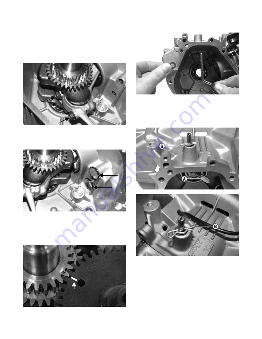
NOTE: When installing the connecting rod to the
crankshaft, rotate the crankshaft so the rod journal is
in the 6 o’clock position to allow access for installing
the rod end cap.
4. With the connecting rod, end cap, and crankshaft
journal lubricated with engine oil, install the con-
necting rod and rod end cap to the crankshaft and
secure with the cap screws. Tighten evenly to 106
in.-lb.
IO080A
5. Apply lightweight oil to the tappets; then install the
tappets to the proper guides as noted during disas-
sembly.
IO079A
6. Apply oil to the camshaft lobes and running surfaces
on each end of the shaft; then with the crankshaft/
piston rotated to TDC and the timing marks of the
crankshaft gear in-line with the camshaft gear, install
the camshaft.
IO078A
7. Install the washer onto the governor control shaft and
slide the shaft up into position from inside the crank-
case far enough to install the hairpin clip.
IO101
NOTE: When installing the governor control shaft,
position the shaft so the flat end (A) of the shaft is
directed to the cylinder (3 o’clock position) and the
hairpin clip (B) is in contact with the crankcase. This
limits the inward movement of the control shaft.
IO082B
IO093A
8. Install the shim washer to the crankshaft and place
the dowel pins and a gasket into position.
Summary of Contents for 2018 ZR 200
Page 1: ......
Page 66: ...65 Wiring Diagram 0752 220 ...
Page 67: ...66 NOTES ...
Page 68: ...67 NOTES ...
Page 69: ...68 NOTES ...
Page 70: ......


