3-8
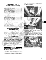
13. Remove the muffler; then remove the exhaust pipe.
14. Set the parking brake; then from the underside of the
vehicle, remove the cap screws securing the drive-
shafts to the drive couplers.
NOTE: Remove the front driveshaft first or the park-
ing brake will not hold the coupler stationary and cap
screw removing will be more difficult.
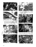
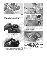
15. Remove two flange nuts from the underside of the
rear engine mounts.
PR153A
16. Remove two flange nuts securing the engine mount-
ing bracket to the front engine mounts.
PR147
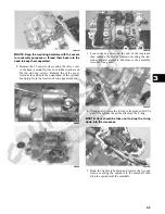
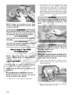
17. Attach suitable lifting chains to the engine/transmis-
sion; then using an engine hoist, lift the assembly out
of the engine compartment.
PR114
NOTE: The front engine mounting bracket should
slide free of the engine mounts first; then the rear
engine mounting bracket and two rear engine mounts
will lift free of the frame.
PR146
Top-Side Components
NOTE: For efficiency, it is preferable to remove and
disassemble only those components which need to be
addressed and to service only those components. The
technician should use discretion and sound judgment.
NOTE: The engine/transmission does not have to
removed from the frame for this procedure.
Removing Top-Side
Components
A. Valve Cover
B. Cylinder Head
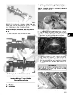
NOTE: Remove the spark plug and timing inspec-
tion plug; then using an appropriate wrench, rotate
the crankshaft to top-dead-center of the compression
stroke.
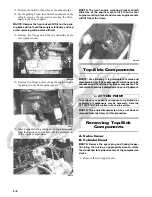
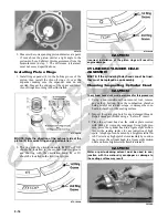
1. Remove the two tappet covers.
AT THIS POINT
To service any one specific component, only limited dis-
assembly of components may be necessary. Note the
AT THIS POINT information in each sub-section.
Summary of Contents for 2013 Prowler XT
Page 1: ...Prowler XT XTX XTZ ...
Page 3: ......
Page 5: ......
Page 149: ...4 16 NOTES ...
Page 211: ...7 8 NOTES ...
Page 232: ...8 21 8 NOTES ...
Page 233: ... Printed in U S A Trademarks of Arctic Cat Inc Thief River Falls MN 56701 p n 2259 530 ...

