3-90
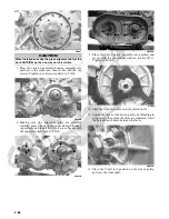
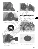
7. Remove the driveshaft (G); then remove the counter-
shaft assembly (with shift forks) (H). Account for
two flat washers on the countershaft.
GZ280B
8. Remove the reverse idler gear (I), shaft bushing, and
two washers.
GZ279
NOTE: Do not disassemble the countershaft assem-
bly unless necessary. If necessary, see Servicing
Center Crankcase Components sub-section.
Servicing Center
Crankcase Components
NOTE: Whenever a part is worn excessively,
cracked, damaged in any way, or out of tolerance,
replacement is necessary.
SECONDARY OUTPUT DRIVE
GEARS
Initial Set-Up
NOTE: If the secondary output driven shaft is
replaced or disassembled, the initial set-up must be
performed to establish correct gear tooth contact. If
only the secondary output driveshaft or secondary
output driven gear are replaced, proceed to Correct-
ing Backlash in this sub-section.
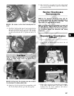
1. Install a new bearing (A) onto the secondary driven
shaft (B) making sure the bearing locating groove is
directed away from the driven gear splines.
MT011A
2. Using a suitable press, install the driven gear (C) on
the shaft until the gear firmly seats on the shoulder of
the shaft.
MT011B
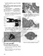
3. If installing the existing shaft, start with the shims
removed during disassembly or if installing a new
shaft, start with approximately 1.0 mm shims at point
(D); then install the output driveshaft bearing (E)
making sure the locating pin is directed toward the
center of the shaft.
MT012
Summary of Contents for 2013 Prowler XT
Page 1: ...Prowler XT XTX XTZ ...
Page 3: ......
Page 5: ......
Page 149: ...4 16 NOTES ...
Page 211: ...7 8 NOTES ...
Page 232: ...8 21 8 NOTES ...
Page 233: ... Printed in U S A Trademarks of Arctic Cat Inc Thief River Falls MN 56701 p n 2259 530 ...


