8-5
8
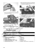
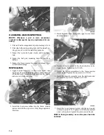
1. Support the vehicle on appropriate stands or a lift;
then remove the left front wheel and left front shock
absorber.
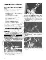
2. Remove the front storage box; then disconnect the
two electrical connectors from the EPS assembly.
PR759A
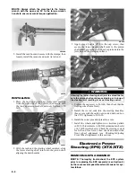
3. Remove the cap screw securing the intermediate
shaft yoke to the EPS assembly input shaft.
PR760A
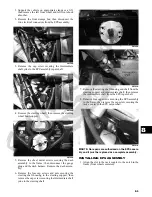
4. Remove the steering wheel; then remove the steering
wheel boot support.
PR762A
5. Remove the sheet metal screws securing the dash
assembly to the frame; then disconnect the gauge
plug and the dash harness. Remove the dash assem-
bly.
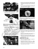
6. Remove the four cap screws and nuts securing the
steering shaft housing to the steering support; then
remove the cap screw securing the intermediate shaft
yoke to the steering shaft.
PR764A
PR765A
7. Remove the steering shaft housing and shaft from the
steering support and intermediate shaft; then remove
the intermediate shaft from the EPS input shaft.
8. Remove four cap screws securing the EPS assembly
to the frame; then remove the cap screw securing the
rack coupler to the EPS output shaft.
PR761A
NOTE: No repairs are authorized on the EPS assem-
bly and it must be replaced as a complete assembly.
INSTALLING EPS ASSEMBLY
1. Align the slot in the rack coupler to the notch in the
frame (front wheels centered).
Summary of Contents for 2013 Prowler XT
Page 1: ...Prowler XT XTX XTZ ...
Page 3: ......
Page 5: ......
Page 149: ...4 16 NOTES ...
Page 211: ...7 8 NOTES ...
Page 232: ...8 21 8 NOTES ...
Page 233: ... Printed in U S A Trademarks of Arctic Cat Inc Thief River Falls MN 56701 p n 2259 530 ...


