6-12
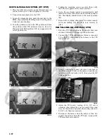
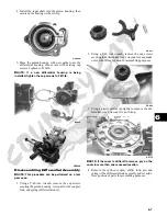
2. Place the ring gear with selected shim into the cover
and measure the ring gear to thrust button clearance
with a thickness gauge. Clearance should be
0.002-0.004 in.
GC058A
3. If clearance is as specified, remove the ring gear and
thrust button; then place a drop of red Loctite #271
on the threads and tighten to 8 ft-lb (left-hand
threads).
4. If clearance is not as specified, repeat steps 1 and 2
using thicker (clearance too great) or thinner (clear-
ance too small) until correct specification is reached.
Assembling Differential Assembly
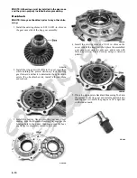
1. With the pinion gear and new bearings installed,
place the selected (backlash) shim on the gear case
side of the ring gear with the chamfered side toward
the ring gear; then install into gear case/differential
housing.
GC031A
GC020
2. Place the selected (end-play) shim, chamfered side
toward the gear, onto the cover side of the ring gear.
GC036B
NOTE: The spider and ring gear assembly must be
replaced as a complete unit.
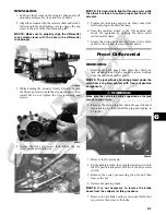
3. Assemble the fork and sliding collar into the cover
assembly; then install the left bearing flange/bearing
assembly and seat firmly into the cover.
CF266A
CF267A
4. Apply a liberal coat of grease to the O-ring; then
install it on the assembled cover assembly making
sure to seat the O-ring completely down around the
circumference of the bearing flange.
Summary of Contents for 2013 Prowler XT
Page 1: ...Prowler XT XTX XTZ ...
Page 3: ......
Page 5: ......
Page 149: ...4 16 NOTES ...
Page 211: ...7 8 NOTES ...
Page 232: ...8 21 8 NOTES ...
Page 233: ... Printed in U S A Trademarks of Arctic Cat Inc Thief River Falls MN 56701 p n 2259 530 ...

