8-10
PR313A
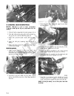
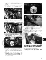
2. Apply green Loctite #270 to the cap screw; then
install the cap screw in the upper steering shaft joint.
Install the nut and finger-tighten.
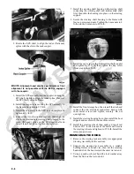
3. Align the match marks on the steering wheel shaft
and the steering wheel and slide the steering wheel
onto the splines; then install the nut and fin-
ger-tighten.
PR696
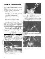
4. Hold rearward pressure on the steering wheel and
tighten the cap screw (from step 2) to 36 ft-lb.
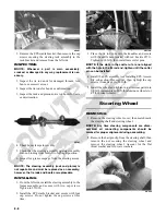
5. Remove the steering wheel nut. Apply one drop of
red Loctite #271 to the threads and install the nut.
Tighten to 25 ft-lb; then install the hairpin clip.
NOTE: If the hole in the steering shaft does not
align with the slots in the castle nut, tighten the nut
slightly until the next slot aligns with the hole.
PR684A
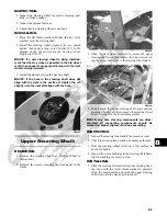
6. Check for freedom of movement of the steering sys-
tem; then install the steering wheel cover.
7. Move the dash panel into position and secure to the
frame and with the existing hardware.
PR181A
Lower Steering Shaft
Assembly
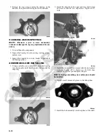
REMOVING
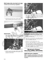
Remove the cap screw securing the lower steering shaft
joint to the pinion shaft; then slide the steering shaft
assembly free and remove through the opening in the
splash panel.
PR304
PR314B
AT THIS POINT
Before beginning this procedure, the upper steering
shaft must be removed (see Upper Steering Shaft in this
section).
Summary of Contents for 2013 Prowler XT
Page 1: ...Prowler XT XTX XTZ ...
Page 3: ......
Page 5: ......
Page 149: ...4 16 NOTES ...
Page 211: ...7 8 NOTES ...
Page 232: ...8 21 8 NOTES ...
Page 233: ... Printed in U S A Trademarks of Arctic Cat Inc Thief River Falls MN 56701 p n 2259 530 ...

