3-91
3
MT008A
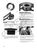
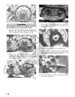
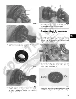
4. Install a new seal (F), output yoke (G), and nut (H)
coated with red Loctite #271 and tighten to 74 ft-lb.
MT008B
NOTE: Do not use a new lock nut at this time as this
procedure may have to be repeated.
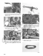
5. Place the assembled shaft into the left crankshaft
case; then lightly coat the gear teeth with machinist’s
lay-out dye. Rotate the shafts through several rota-
tions in both directions. Gear contact should extend
from the root to the top of the gear teeth.
MT016A
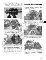
6. To adjust tooth contact, use the following chart to
correctly shim the driven shaft.
7. After correct tooth contact is established, proceed to
Checking Backlash in this sub-section.
Checking Backlash
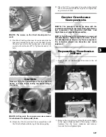
1. Install the drive bevel gear assembly and driven
bevel gear/output shaft assembly into the crankcase
bottom cover.
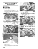
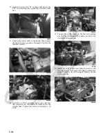
2. Mount the dial indicator so the tip is contacting a
tooth on the secondary drive bevel gear.
GZ396
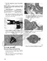
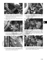
3. Firmly hold the bearing down and while rocking the
drive bevel gear back and forth, note the maximum
backlash reading on the gauge.
GZ398
4. Acceptable backlash range is 0.127-0.381 mm
(0.005-0.015 in.).
Correcting Backlash
NOTE: If backlash measurement is within the
acceptable range, no correction is necessary.
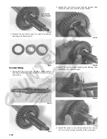
1. If backlash measurement is less than specified,
remove an existing shim, measure it, and install a
new thinner shim.
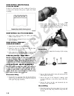
GZ393A
Tooth Contact
Shim Correction
Contact at Top
Increase Shim Thickness
Contact at Root
Decrease Shim Thickness
Summary of Contents for 2013 Prowler XT
Page 1: ...Prowler XT XTX XTZ ...
Page 3: ......
Page 5: ......
Page 149: ...4 16 NOTES ...
Page 211: ...7 8 NOTES ...
Page 232: ...8 21 8 NOTES ...
Page 233: ... Printed in U S A Trademarks of Arctic Cat Inc Thief River Falls MN 56701 p n 2259 530 ...


